Design Surface Road Reference Line
The Create Surface Roads screen is used to create roads on a reference topography, using a reference line and various parameters describing road profile and cut and fill batters.
After running the command, the Create Surface Roads dialog is displayed in a dockable control bar.
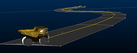
A surface road with highlighted centreline
Create a Surface Road Centerline
Each surface road is generated from a string representing the road reference line. A reference line is required before the Generate Road option becomes available.
This can be created directly within the command, or copied from any loaded string object:
- Type: decide if your reference line will represent the road Centerline, Left Edge or Right Edge. The left and right options are consistent with the direction of the string.
- New: click New to digitise a new string, using the same mechanism as thenew-string command.
Tip: for precise road specification, you can use the command line to enter specific absolute or relative vertex coordinates. See Command Line Coordinates.
-
Copy: select an existing reference line from the 3D view, by clicking on it with the cursor. Note that a copy is made of the reference line and the original reference line hidden from the view.
Attributes will not be copied from the original reference line . However, if the reference line is one produced from another session of the Create Surface Road tool, then you are asked; “Do you want to copy the road information from this reference line?”. If the answer is “Yes”, then the screen is updated to the parameters last used with that reference line, and the road name will also be changed accordingly. Answering “No” continues with the current settings.
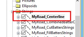
However created, a new object called [Road Name]_ReferenceLine is created to store the centreline data

Vertical and Horizontal Centerline Adjustment
Road reference line data can be adjusted either using a horizontal
or vertical adjustment of string vertices. The type of editing is
determined by expanding either the Reference
Line Horizontal Adjustment or Reference
Line Vertical Adjustment command groups.
Reference Line Horizontal Adjustment
The Reference Line Horizontal Adjustment expanding group contains shortcuts to common commands used to edit the reference line. Expanding this group makes the 3D view the current view.
In most cases shortcut buttons will ensure the reference line is the only string selected, so that the commands only work on that string. Editing the reference line is not restricted just to the commands offered; it is possible to use any other string editing command to modify the reference line, including any which change the string’s elevation. However, there is a dedicated view and set of commands for working with gradients and elevation in the Reference Line Vertical Adjustment mode (see below).
The following tools are available in the Reference Line Horizontal Adjustment group:
- Insert Points
- Insert Line
- Insert Curve
- Move Point
- Move Section
- Transform
- Delete Points
- Smooth
- Fillet All Points
- Fillet Point
- Condition
Warning: edits to the reference line cause previously calculated downstream results (if any exist) to be removed. These will need to be regenerated either interactively or by enabling the Auto Apply setting to subsequent creation steps.
Reference Line Vertical Adjustment
The Reference Line Vertical Adjustment group also contains shortcuts to common commands. However, rather than acting upon the reference line in the 3D view, a special Road Elevation view, which is created automatically when the group is expanded, is displayed. This view is automatically oriented to make vertical centerline point adjustment easy and will show the reference line and an intersection of the loaded topography for reference, for example:
The Road Elevation view contains a long section along the road reference line. The horizontal axis of this view is always horizontal distance along the road, and is not related to a given world axis such as Easting or Northing. The topography is shown as a green dashed line, and represents the topography directly above or below the road reference line.
If the reference line does not run entirely within the bounds of the topography, no topography is shown in this view, and a message will shown in the cut and fill volume report.
The display in the Road Elevation view is linked to the reference line string in the 3D view. Any edits to the reference line string in the 3D view will update the display in the elevation view, and the 3D centerline will also update in response to edits in the elevation view.
The Reference Line Vertical Adjustment expanding group contains shortcuts to common commands used to edit the road elevations. Expanding this group makes the Road Elevation view the current view. In most cases shortcut buttons will ensure the road profile string is the only string selected, so that the commands only work on that string.
Road segments that violate the current gradient constraints are show in red, for example, in the image below 3 road sections have a steeper gradient per measurement unit than permitted:
Editing the road profile string is not restricted just to the commands offered - it is possible to use any other string editing commands to modify the road profile.
Note: vertical adjustment commands may change both point elevations and distance along the road. Because distance can only ever increase, any attempt to move points out of sequence is corrected – possibly leading to vertical road segments.
Points inserted into the road profile or moved along the road profile will honour the current horizontal profile of the road as seen in the 3D view. Any points on the horizontal profile, but not on the elevation profile, are retained and have their elevation match the elevation profile.
The following tools are available in the Reference Line Horizontal Adjustment group:
- Fit to Surface
- Insert Points
- Insert Line
- Insert Curve
- Move Point
- Delete Points
- Smooth
- Smooth Gradient
- Adjust Gradient
- Fillet All Points
- Fillet Point
Related topics and activities


