Surface Road Sections and Parameters

The Create Surface Roads screen is used to create roads on a reference topography, using a reference line and various parameters describing road profile and cut and fill batters.
After running the command, the Create Surface Roads dialog is displayed in a dockable control bar.
Surface road cross-sections can be applied either as a default (flat) profile along the entire length of the road, a constant shape or as a series of shapes that can be picked from a library.
Simple Road Design
Simple roads use the default road width along the entire length, and use the same road cross section at every point. This may be level or include an optional crossfall (always defined as a percentage). An optional central windrow may also be optionally defined. Note that the defined road width is including the width of any windrow. Simple roads can be a good choice for small cuts or ramps where complexity of library-based roads is not required.
Using
a Library of Cross Sections
The From library option allows roads to be created from a variety of customised cross-sections. Crown and edge cross-sections can vary at any point along the string to create exactly the profile required. Note that when using the library option, defined road cross-sections override the default road width.
Cross section library data
The library is a loaded string file which containing various cross-section profiles.
Each cross-section needs a unique ID, stored in a RDPROFID data column. Separate cross-sections can be defined for the road crown and road edges. This allows different edges to be applied depending on whether the edge of the road is in a cutting (for example; drainage) or has a drop (for example; windrows).
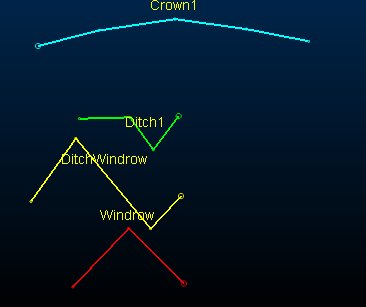
All strings should be created in the XZ plane; Y values are ignored. For example, the following library file contains four cross section shapes (the RDPROFID label is applied to each string)
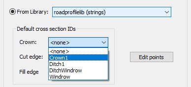
Once loaded, the section shapes become available in the Create Surface Roads task by enabling the From Library option and expanding the drop-down list for the Crown, Cut edge or Fill edge locations, for example:
Crown cross sections
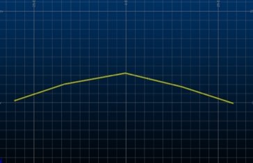
Crown cross-sections define the cross section of the road and are applied at reference line points. The x axis of the cross section runs from the left of the road to the right, when looking from the start of the string forwards along the string. The XZ location of the crown string is important; the 0,0 point will always be placed on the centerline of your road.
For example, the above crown profile applied to all points of the
road could look like this: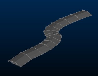
Edge cross sections
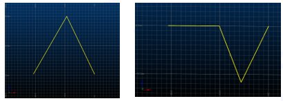
Edge cross-sections are applied to the open ends of the crown cross-section. As with crown cross-sections, edges are defined in the XZ plane. However, unlike crown cross-sections, the actual position is not important; the edges profiles will always be repositioned so they start at the end of the crown cross-section. Edge profiles should be defined as though they are on the right hand side of the road. They will automatically be reversed when used on the left side.
Cut and fill edge profiles may be different. The type of edge profile used is chosen automatically based on whether the end of the crown cross section is below (cut) or above (fill) the topography.
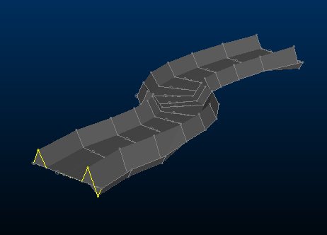
For example, using the above windrow and ditch-windrow profiles (but no crown specification), a road shape similar to the following could be generated:
Note: if an edge cross section is not chosen, then no edge is added to the cross section. If a crown cross section is not chosen, then a simple flat crown profile of the default road width is used instead (as shown above).
The real power of the cross section library come in applying different cross sections at different points along the centreline, for example to provide passing points, super-elevations or gaps in windrows for drainage.
Editing section points
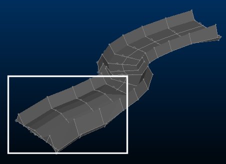
The Edit points button displays a new dialog allowing you to select points along the centerline and assign specific values to them. In the above example, a crown profile has been applied to the first four centerline points only, leaving a flat profile for the remainder of the road.
The Set Road Cross Section dialog is displayed, allowing you to assign either a crown or edge (cut or fill) section ID to selected points in the 3D window.
Overlapping Road Sections
Depending on the shape of your road and how sections are generated, it is possible for sections to overlap at certain points, e.g. where the direction of the road changes sharply. Your application detects and handles this situation automatically; if road cross sections are found to be crossing over, those crossovers are ignored and a simple digital-terrain-model calculation used to generate the road surface.
Where this occurs, the generated road section is displayed
in red, for example: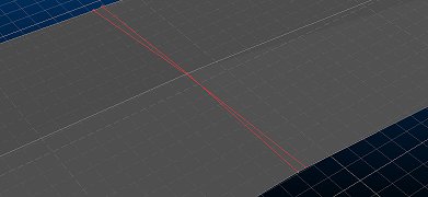
Choosing which surface road data to generate
By default, three objects are created for each generated surface road:
-
A road outline
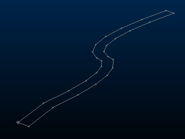
This represents the outer hull of the road shape.
-
Road cross section(s)
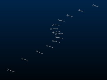
One or more strings are produced that represent the cross sectional profile of the road at predetermined points. If a simple road is used, this is a repeated straight line section representing the width of the road, otherwise string data representing library-picked cross-sectional shapes are generated.
-
A road surface wireframe
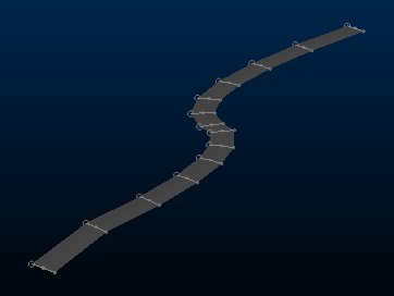
An open surface representing the 3D road. This is integrated with the topography using batters.
This data is generated independently of the selected topography. Topography modification (and final cut and fill volume calculation) is available once road batters have been defined and generated.
Related topics and activities

