Surface Road Cross Sections
To access this screen:
-
Using the Create Surface Roads task, generate or select a centerline and, in the Road Parameters control group, select a cross section library and click Edit Points.
Select points along the road reference line and assign specific cross sectional shapes to them.
You can assign either a crown or edge (cut or fill) section to selected reference line points in the 3D window. Your road reference line should be visible before you start to use this dialog (you can enable it using the Surface Roads Toolbar).
This screen works in conjunction with any Default crown or edge profile shapes set in the parent Create Surface Roads task.
Note: the Set Road Cross Sections screen is not required if you wish to apply the same crown and edge profiles to the entire road. In the absence of any per-reference-line-point section settings, the default values are applied throughout the road when Generate Road is selected.
The checkboxes on the left control which values are written to the road reference line points. In addition to the named cross sections, points may be reset to tracking the default cross section IDs, by using the <default> option.
To assign cross sectional shapes to centreline points:
- Displaying the road reference line.
- Selecting the crown and or edge shapes to be applied to reference line points.
-
Selecting the reference line points to be modified. Points are selected using the click or box drag mechanism, supporting the use of the <CTRL> key to extend or toggle the existing selection.
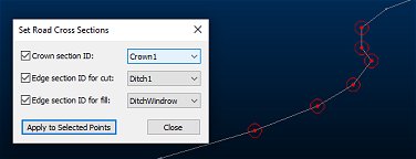
Selected (but unchanged) points are highlighted in red, for example.:
-
Click Apply to Selected Points.
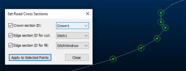
Modified points are highlighted in green, for example:

This appends the reference line string object with section ID information. - Clicking Close to return to the Create Surface Roads dialog.
- Clicking Generate Road to (re)create the specified output objects.
Related topics and activities


