Autolayout: Create Curve
To use this autolayout action:
-
Edit Automated Design Rules screen >> Action >> Create Curve.
This autolayout action is used to introduce a curved line from the start or end of qualifying string data in an assigned design data file.
Curves can be either a quarter, half or full turn. The starting azimuth and gradient are configurable, as is the radius of the curve. You can also define an offset from the starting position if required.
Create Curve Example
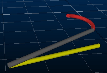
For example, the 2-point design string below represent an access drive.
The end of a decline is being designed, as a half curve, rising at a 15 degree gradient. The starting azimuth matches the string (35 degrees). A turning radius of 40m is required.
In this example, the Create Line Settings dialog contains the following values:
- Radius: 40
- Curve Direction: Anticlockwise
- Entry Azimuth: 35 (world)
- Gradient: 15 (degrees)
- Start Position: End
- Distance from Start Postion: 0.00
After processing, the design data is appended with a new string segment (in this example it was connected to a DECLINE design definition and is shown in red). Perspective 3D formatting has been added to highlight the orientation of the new string segment and a yellow segment is added to show the ground plane:
As well as defining the ramp start and progression parameters as shown above, you can also take control of how the road angle sweeps between start and end locations. You do this using the End Limit too group below. These are the exclusive options for defining how/when a road turns and terminates whilst adhering to the curve settings above:
- Choose a definitive Sweep Angle (default = 90) to enforce a road turn. This must be a positive value.
- Define the Exit Azimuth of the ramp (in relation to the 3D world).
- Enter the Distance the road will continue either in a [Horizontal], [Vertical] or continued [Slope] direction.
Regardless of the chosen option, you can add zero or more full 360-degree spirals to your road, adding to whatever angle is swept by the above options.
Autolayout Action Options
The Create Line Settings screen displays the following options:
-
Radius – The turning radius of the curve in world measurement units.
-
Curve Direction – Can be Clockwise or Anticlockwise
-
Azimuth – Enter the azimuth of the new curved string section. This can be set as a real-world azimuth or in relation to the existing design data (relative).
-
Gradient – Specify the gradient of the new string n either degrees, % or a ratio.
-
Start Position – Choose to add a curve to either the start or the end of qualifying design data.
-
Distance from Start Position – Specify a positive or negative distance to offset the start of the curve from the start or end of design data.
-
End Limit – See above for more details, but in brief:
-
Sweep Angle – The angle of the final curve of the ramp will cover, in addition to any full spirals specified (see below).
-
Exit Azimuth – The azimuth at which the ramp will terminate.
-
Distance – The distance projected for the ramp in either a [Horizontal], [Vertical] or [Slope] direction.
-
Add Spirals – Add some extra decline or incline spirals to your ramp here. These will be applied in addition to the other End Limit settings above.
-
Related topics and activities


