
Edit Automated Design Rules
To access this screen:
-
On the Design panel, click Edit Automated Design Rules.
Set up automated design rules.
Your should use a three-step approach to using automated design rules:
-
Set up one or more rules that apply to a pre-defined filter. Each group of rules is referred to as a "rule set". These rules are defined using the Edit Automated Design Rules screen.
-
Assign each rule set to a data design file. All design files currently associated with the project (via the Settings panel) can be used as a basis for automated design. Rule sets are assigned to design files using the Assign Automated Rules Sets dialog.
-
Process the rules to generate activity points and solids.
Note: This screen includes table grids that support multiple row selection.
Creating Rule Sets
Rules are categorized within rule sets. These are defined using the left side of the dialog. For each set, one or more rules is defined on the right. Select a rule set to edit its rules.
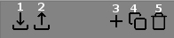
- Import an XML file containing rule set information.
- Export an XML file containing rule set information - useful for standardizing on rule sets throughout an organization.
- Add a new, empty, rule set
- Copy the currently selected rule set .
- Delete a rule set . Note that this is only possible if the rule set has not already been assigned to design data. Once assigned, a rule set will be locked.
You can edit the name of any (unlocked) rule set by typing over it.
Creating Rules
Once a rule set has been selected on the left of the dialog, you can start to define rules. At least one rule must be present, so a default rule will be created for every new rule set, which can be modified and appended (if required) with additional rules.
Autolayout rules contain the following elements, each represented by a table column,
-
A Number. This is an important index as it defines the order in which the rule will be processed. Where rules rely on the output of previous rules, incorrectly numbered rules can cause missing dependency problems and unexpected results.
Note: Only one rule set can be associated with a design data file. As such, you should make sure that each rule set contains correctly ordered rules.
- An Action. This defines what is either modified or created when the rule is applied. You can see a full list of actions and links to more details below. A simple example of an action is shown further below (Create Line).
-
An Input Filter. By default, every string entity within an assigned design string file will be modified by the rule. For example, if you specified a [Reverse] action, all strings within the design file would be reversed.
Note: Specifying a filter allows you to constrain the rule to a subset of data. This can be set using any custom or system filter, including by design type, design definition or group position.
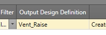
- An Output Design Definition. Data that is created will be assigned any predefined design definition. Select the design definition that represents the automatically-designed string data using this drop-down list.
-
Settings. These determine how the design data is constructed, and will vary depending on the Action specified. For example, if you are creating a new string at the end of a previous one (Create Line), you can specify the length, azimuth, gradient and offset for the new string. See "Autolayout Actions", below, for more details.
Settings are defined using the Create Line Settings screen.
- Use. You can define rules and disable them for future use if you like. If this check box is enabled, the rule will be processed, otherwise it won't.
Add as many rules as you need - they are processed in order.
Autolayout Actions
The following automated layout actions are available. Select a link for more information:
- Break at Intersections
- Break at Intervals
- Create Curve
- Create Line
- Create Line Between
- Create Multiple Lines
- Create Stope Crosscuts
- Extend Strings
- Project Strings to Wireframe
- Reverse
- Translate
- Trim Ends
- Trim to Perimeter
- Trim to Wireframe
Simple Autolayout Example (Create Line action)
In the following example, a two-point FXS design string representing a stope access centreline is used to locate a new string section representing a ventilation shaft. The shaft begins at the end point of the drive string and projects vertically. The two point string object (contained in "autodesignFXS.dm") has already been added to the project using the Settings panel.
The project in this example contains several design definitions, including one to represent a stope access drive and another for a vent raise.
Note: The Create Line action modifies a design string object by adding a new string entity to the table. The existing string data within the assigned object (in this case a table representing a subset of drive strings) won't be modified. Other actions can be used to modify existing data (such as extending a string, for example, or projecting it to a wireframe).
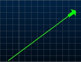
This is the original access string, located on a horizontal plane (an arrow symbol has been added to show the string direction):
Here's the autolayout example:
-
Activate the Design panel and locate the Automated Design control group.

No autolayout rules or rule sets have yet been defined for this project.
-
Load your design data (button 1, below):

- Open the Edit Automated Design Rules screen.
-
Rule sets are shown on the left, rules for the selected set on the right. On the left of the dialog, click "+" to add a new rule set to the list:
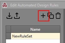
- You can edit the name of the rule set by over-typing. In this case, it is changed to "Stope_Vent_Ruleset".
-
On the right, a table row has been created with some default entries:

Note: A rule set must have at least one rule.
- In this example, the default Action is correct ([Create Line]).
-
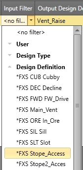
The Input Filter is set to <no filter>, meaning it will be applied to the assigned string object in its entirety. For example, if there were 3 open 2-point strings in the design file (as opposed to one in this example), a ventilation raise string would be applied to all of them.
You can apply your rule to a subset of data by filtering. The FXS design string in this example has been connected to a "Stope_Access" design definition. Although filtering isn't necessary in this example, the filter is changed to a design definition representing a stope access string:
-
The data being created represents a ventilation shaft, and a design definition already exists for this, so it is selected using the Output Design Definition drop-down list:
-
The design of the output ventilation string is defined using the Settings column. To access the settings for the raise, the Create Line Settings screen is launched:

-
The shaft will be 100m in length, at a gradient of 90 degrees. It will start from the end of the stope access string without any offset. The Create Line Settings dialog is filled out like this:

- Click OK to return to the Edit Automated Design Rules screen.
- OK dismisses the Edit Automated Design Rules screen.
-
As it is, the rule has been defined, but not assigned to design data.
To do this, the Edit Automated Design Rule Assignments screen is used:

-
A list of file names appears on the right - these are all design string files associated with your project, for example:
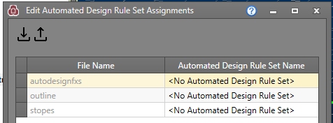
- In this case, the "autodesignFXS" file is being used to construct an automated layout. Select the corresponding Automated Design Rule SetName option [Stope_Vent_Ruleset] to associate the design data with the rule set created previously.
- Click OK.
- In the Design panel (Automated Design group) click Go to process the autolayout rules.
- Click Show Output to see
the progress results and review the design data in the 3D
window:
- Save your design data.
-
Continuing the example to show multiple rules, you can delete the newly-created string (select it in the 3D window and press DELETE) and return the original Stope_Vent_Ruleset and add another rule below the original.
The original 2 point string remains in view.
-
You can define another rule, again using Create Line with <no filter> lets you specify more settings. Create a line, 60 units long, at a zero gradient, to the end of qualifying strings (this time, there will be two strings as one will be added using the initial rule):

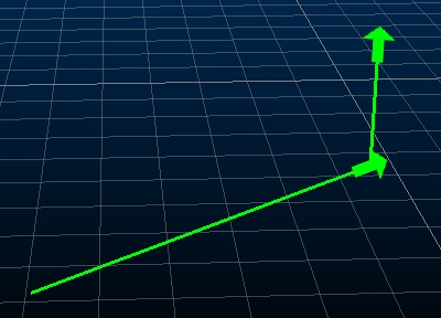
- Process these rules and you'll see that three new strings are generated:
- First, the vertical 200m raise is added to the end of the stope access (horizontal) design string
-
Then a 60m service channel is added to the end of both the new vent raise and the stope access string

Related topics and activities