
Automated Designs
Studio UG provides automated tools that offer an alternative to a manual design approach. Using logical rules and constraints specific to the mine, the Autolayout tool can be used to modify and generate design string data prior to processing and assign a design definition to additional data items.
Adopting an automated approach means that a mine layout may be altered significantly and quickly and easily to facilitate scenario analysis and/or changes in geological structure. Studio UG generates a mine design within the specified framework based on a set of rules that are sympathetic to these geological, geotechnical or operational constraints.
Automated design applies to a range of mining methods. Box and pillar method is an obvious application, but any mine design can, potentially, have a number of repetitive logical design decisions that can be created by rules. Assessing the impact of different stope sizes on the position of accesses, for example, could be made a lot quicker and easier with the specification of some design rules. Scenario analysis then becomes a case of editing the relevant rules and reprocessing.

An example of the considerations for automated design.
The automatic layout facility allows you to reduce much of the repetitive, manual work associated with creating a mine layout. Automatic layout rules are set up to either create new design strings or edit existing ones. Each rule applies to a particular design type and will be applied to all strings of that design type.
You can use a combination of automated and manual design methods.
Realistically, a combination of both automatic and manual layout design
operations are the most likely scenario. You could simply use this
facility to perform isolated activities such as trimming design strings
or adding stockpiles to a decline development, for example.
Your should use a three-step approach to using automated design rules:
-
Set up one or more rules that apply to a pre-defined filter. Each group of rules is referred to as a "rule set". These rules are defined using the Edit Automated Design Rules screen.
-
Assign each rule set to a data design file. All design files currently associated with the project (via the Settings panel) can be used as a basis for automated design. Rule sets are assigned to design files using the Assign Automated Rules Sets dialog.
-
Process the rules to generate activity points and solids.
Rules can be defined even if you don't need them right away. Create them and disable their Use setting until you do.
See Editing Automated Design Rules.
Automated Design Prerequisites
Before you start an automatic layout, you need to have completed the following tasks:
- You may need design strings specified (they don't need to be loaded) to form the 'backbone' of your mine design. If generating crosscuts automatically, stope wireframes must be assigned to the project.
- Defined attributes, naming conventions, and derived activities as required.
-
You will also need to have created any design definitions (including cross-section definitions) that may be applied to design strings in the autolayout process.
Here are some useful rules when creating automated designs
Automated Design Actions
Studio UG offers several options for what to do when design data qualifies for automation.
These actions represent automated digitizing functions to be applied to any data that matches a predefined filter. The new data is then connected to an existing design definition (which ultimately controls how solids and activity points are generated).
Each action can be configured. For example if you choose to extend all cubby strings using the "Extend Strings" action, you can define the amount of extension in the Create Line Settings screen. Similarly you can choose which end of the qualifying string(s) to extend, amongst other parameters.
To find out more about the parameters available for each autolayout
action, select a link below:
- Break at Intersections
- Break at Intervals
- Create Curve
- Create Line
- Create Line Between
- Create Multiple Lines
- Create Stope Crosscuts
- Extend Strings
- Project Strings to Wireframe
- Reverse
- Translate
- Trim Ends
- Trim to Perimeter
- Trim to Wireframe
Defining Autolayout Rules
Automated design rules are created using the Design panel.
Once rules are defined, their corresponding rule set is associated with a design file. This can be any design string file represented within the project (as displayed on the Settings panel).
These rule sets are then processed to update the design file(s) accordingly. Where new data has been created, it will be assigned a design definition (as determined by the underlying rule for that data).
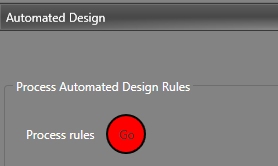
If a valid rule set has been defined, the Automated Design control group displays an active Process Rules button:
During processing, you will see a series of messages displayed to indicate the progress of design string modification.
Note: Design data must be loaded to process autolayout rules.
The amount of time processing takes depends on the complexity of affected design data and the rule sets being applied. As with other progress dialogs in Studio UG, information is split into Information, Warnings (unusual but non-critical output) and Errors (output that may cause problems in walls and points generation).

The modified design data is displayed in the 3D view. If you're happy with the result, you can save it using the button in the top right corner of the panel.
Simple Autolayout Example (Create Line action)
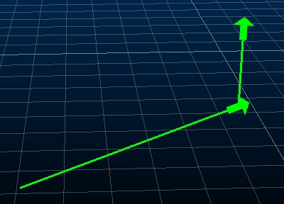
In the following example, a two-point FXS design string representing a stope access centreline is used to locate a new string section representing a ventilation shaft. The shaft begins at the end point of the drive string and projects vertically. The two point string object (contained in "autodesignFXS.dm") has already been added to the project using the Settings panel.
The project in this example contains several design definitions, including one to represent a stope access drive and another for a vent raise.
Note: The Create Line action modifies a design string object by adding a new string entity to the table. The existing string data within the assigned object (in this case a table representing a subset of drive strings) won't be modified. Other actions can be used to modify existing data (such as extending a string, for example, or projecting it to a wireframe).
This is the original access string, located on a horizontal plane (an arrow symbol has been added to show the string direction):
Here's the autolayout example:
-
Activate the Design panel and locate the Automated Design control group.

No autolayout rules or rule sets have yet been defined for this project.
-
Load your design data (button 1, below):

- Open the Edit Automated Design Rules screen.
-
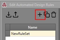
Rule sets are shown on the left, rules for the selected set on the right. On the left of the dialog, click "+" to add a new rule set to the list:
- You can edit the name of the rule set by over-typing. In this case, it is changed to "Stope_Vent_Ruleset".
-
On the right, a table row has been created with some default entries:

Note: A rule set must have at least one rule.
- In this example, the default Action is correct ([Create Line]).
-
The Input Filter is set to <no filter>, meaning it will be applied to the assigned string object in its entirety. For example, if there were 3 open 2-point strings in the design file (as opposed to one in this example), a ventilation raise string would be applied to all of them.
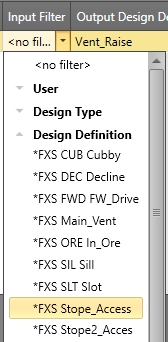
You can apply your rule to a subset of data by filtering. The FXS design string in this example has been connected to a "Stope_Access" design definition. Although filtering isn't necessary in this example, the filter is changed to a design definition representing a stope access string:
-
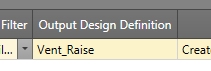
The data being created represents a ventilation shaft, and a design definition already exists for this, so it is selected using the Output Design Definition drop-down list:
-
The design of the output ventilation string is defined using the Settings column. To access the settings for the raise, the Create Line Settings screen is launched:

-
The shaft will be 100m in length, at a gradient of 90 degrees. It will start from the end of the stope access string without any offset. The Create Line Settings dialog is filled out like this:

- Click OK to return to the Edit Automated Design Rules screen.
- OK dismisses the Edit Automated Design Rules screen.
-
As it is, the rule has been defined, but not assigned to design data.
To do this, the Edit Automated Design Rule Assignments screen is used:

-
A list of file names appears on the right - these are all design string files associated with your project, for example:
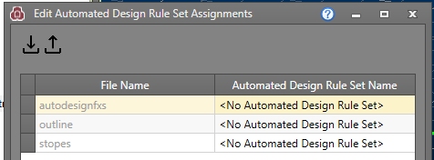
- In this case, the "autodesignFXS" file is being used to construct an automated layout. Select the corresponding Automated Design Rule SetName option [Stope_Vent_Ruleset] to associate the design data with the rule set created previously.
- Click OK.
- In the Design panel (Automated Design group) click Go to process the autolayout rules.
- Click Show Output to see
the progress results and review the design data in the 3D
window:
- Save your design data.
-
Continuing the example to show multiple rules, you can delete the newly-created string (select it in the 3D window and press DELETE) and return the original Stope_Vent_Ruleset and add another rule below the original.
The original 2 point string remains in view.
-
You can define another rule, again using Create Line with <no filter> lets you specify more settings. Create a line, 60 units long, at a zero gradient, to the end of qualifying strings (this time, there will be two strings as one will be added using the initial rule):

- Process these rules and you'll see that three new strings are generated:
- First, the vertical 200m raise is added to the end of the stope access (horizontal) design string
-
Then a 60m service channel is added to the end of both the new vent raise and the stope access string

Related topics and activities