
Autolayout: Translate
To use this autolayout action:
-
Edit Automated Design Rules screen >> Action >> Translate.
This autolayout action is used to translate qualifying string data in a specified direction over a given distance during autolayout processing. You can either translate a clone of the original string or move string data.
You can also choose to translate string data multiple times. This is useful if you elect to keep the original strings as it can be used to generate equally spaced strings such as those over a regular grid in box and pillar mining.
Translate Example
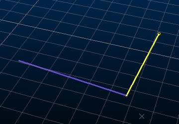
In this example, two design strings exist. Each is connected to a different FXS design definition ("Stope_Access" and "Stope2_Access").
The requirement is to form a grid of strings by projecting one string repeatedly in the X direction and the other in the Y direction. The end result will be 2 lots of 5 overlapping strings, forming a grid of squares, each with 60m sides.
The original FXS design data:
Two rules are needed to generate a grid (one for the horizontal translation of the purple string, and one for the vertical movement of the yellow string). Each rule will include an instruction to repeat the translation 4 times.
Rules are defined using the Edit Automated Design Rules screen.
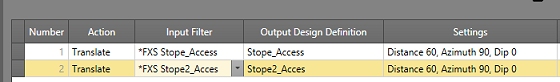
For the purple string (design data connected to the "StopeAccess" design definition), the Action is [Translate] and the Input Filter is [*FXS Stope_Access]]. The output data is also set to [Stope_Access] - although it is possible to change the translated data to another definition.
In the settings dialog, the following settings are used:
- Distance: 60
- Azimuth: 90
- Dip: 0
- Relative To: Design
- Number of Translations: 4
The Relative To setting is important; setting a 90 Azimuth and zero Dip relative to the original design string will create a new string perpendicular to the axis of the two-points of the original string.
The same settings can be used for the purple string, although in this case, the Input Filter and Output Design Definition will be Stope2_Access.
The Edit Automated Design Rules screen looks like this when both rules are defined:
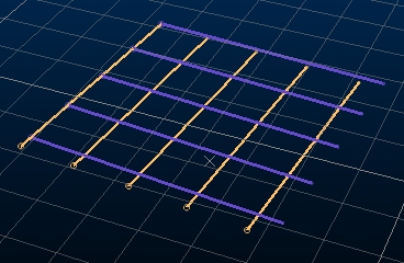
Processing this rule set produces the following output:
Autolayout Action Options
The Create Line Settings screen displays the following options:
Translation Direction
These settings determine the direction in which string data is translated during automated layout calculations:
-
-
Azimuth – Enter the azimuth of the new curved string section. This can be set as a real-world azimuth or in relation to the existing design data using the Relative To options below.
-
Dip – Specify the dip used for translating string data in degrees.
-
Relative to – Choose to base the specified Azimuth and Dip relative to the Design data, or in actual World values.
Translation Distances
String data can be translated by a fixed distance, or you can translate each string within a group by a custom amount along its length, per vertex, using a variable spacing option:
-
Type – Select Fixed (default) or Variable:
-
Fixed ensures all strings generated are projected with the same inter-string distance.
-
Variable lets you define per-string translation distances, potentially varying the spacing between successively translated strings.
-
-
Distance(s) – Either the fixed distance to project string data in world units from the previous one, or the number of translation distances that have been defined for variable spacing (if Variable is selected). To specify variable translation distances, use the browse button to display the Edit Variable Translation Distances screen.
-
Number of Translations – Only available for Fixed translations. By default, a single translation is performed. You can choose any number of repeated translations, which can be useful if you elect to keep original string data (see below, and the example above).
-
Keep Original Strings – If checked (default), the original string data is retained and a translated clone string created. If unchecked, the original string data is removed.
Related topics and activities