
Manual Dependencies
Note: This topic relates to planning activity dependencies.
Manual dependencies are created by linking activity points interactively, selecting the predecessor and the successor of the dependency in that order. Manual dependencies can be generated from any existing activity, in a backwards or reverse direction. You define dependencies between any activity points, regardless of the underlying design type.
Note: You can also set up automatic dependencies.
For example, a segment of an outline solid representing a stope (and containing an activity point) can be instructed to commence only after completion of the terminal activity of the access drive. Similarly, you can link complex solid and wireframe activities, or complex solid and fixed cross sectional activities, as further examples.
Manual dependencies are set by specifying points to indicate the activities to link (therefore applying the activity relationship as defined by the current layer).
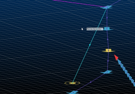
An example of a manual dependency being created between activity points
Dependencies are sometimes required to change direction, opposite to the string. You can do this using the Reverse option then interactively selecting the dependency strings to reverse.
When you've finished, click Save to commit your changes to the UG database. Your changes must be saved before Go is enabled to allow sequencing to be applied.
Use the Project Data group of commands to load planning data, not just activity points and dependency strings. This group lets you independently load reference solids, points, dependencies and design outline data.
Tip: Select the Invalid Dependencies Filter to display troublesome dependency strings for you to correct.
Manual Dependency Editing Methods
There are two ways to manually create dependencies in the primary 3D window:
-
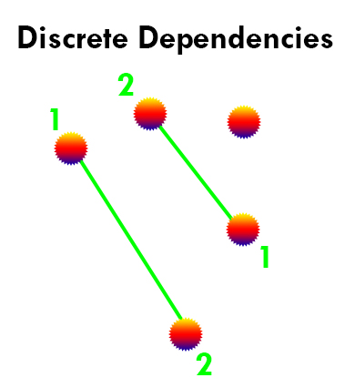
Click two points in the 3D window to define a single dependency. You then get to select further pairs of points if you need to. These are Discrete dependencies and following a click point 1 - click point 2, click point 1, click point 2... pattern.
For example:
-
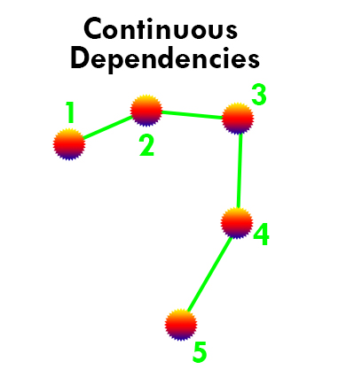
Click a series of points, generating dependencies between successive point positions. These are Continuous dependencies and follow a click point 1, click point 2 (creates 1-2 dependency), click point 3 (creates 2-3 dependency), click point 4 (creates 3-4 dependency)... pattern.
For example:
All dependencies need to reference an activity link type. This will determine the relationship between activities assigned to the selected dependency layer. The following dependency types can be selected:
- Finish-Start – The default dependency type - the preceding activity finishes before the next starts.
- Finish-Finish – The preceding and current activity finish at the same time.
- Start-Start – The preceding and current activity start at the same time.
- Start-Finish – The current activity finishes as the preceding one starts.
- Percent-Overlap – This is a variant of the [Finish-Start] type; the current activity starts when there is a specified % of the preceding activity yet to complete.
Defining the correct relationship between activities is an essential part of planning. For example the following activity points (represented in the DTS Gannt view) shows 7 activities, all specified with a Finish-Start relationship:
Whilst the same activities defined with a Start-Start relationship would all start simultaneously:
Any delay specified here will replace any default layer that may be assigned for the currently selected layer.
The link type is set before a manual dependency is created. It is not possible to change the relationship between activities after a manual dependency has been created (other than by manually editing the underlying dependency table, which is not advised).
To cancel a manual editing mode, click Cancel or press <Esc>. This will end the manual editing session and re-enable panel controls.
Selecting Data to Edit Dependencies
If dependency data exists, there are two ways to edit dependencies interactively using the Reverse, Delete and Apply Defaults options:
- Select the command first, with no 3D window data selected, then pick one dependency at a time to edit it.
- Select the data first (one or more dependencies) then pick a button to apply an edit. This method can be used to edit multiple dependencies simultaneously.
Generated Dependency Data
Generated dependencies data are represented by one or more string objects, where each object represents a particular design definition. These are automatically formatted to make it easier to see what each string represents.
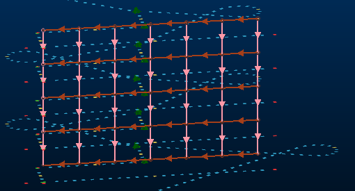
By default, the string direction (clearly important when describing predecessor and successor activity points) is indicated by arrows along each string. These connect activity points, forming a non-negotiable relationship between mining operations (backfill can't start before excavation and mucking out completes, for example).
An example of dependency strings connecting activity points of a decline. The main decline development is indicated by blue arrows (using simple finish-start dependencies based on the string direction) whereas vertical and horizontal directional dependencies are shown in pink and red:
Each dependency string carries useful information in its database, in the form of string attributes aside from the default system fields for strings, including:
-
FROM_NAME – The name of the predecessor activity.
-
TO_NAME – The name of the successor activity.
-
FROM_ID – The internal ID used to identify the predecessor activity.
-
TO_ID – As above, but identifies the successor activity.
-
TYPE – The type of dependency the string represents:
-
FS – Finish to Start
-
SF – Start to Finish
-
SS – Start to Start
-
FF – Finish to Finish
-
PO – Percent Overlap?
See Task Dependencies.
-
-
LAG_QTY – The lag, if any, before the current activity starts following a trigger.
-
LAG_UNIT – The time unit used when describing lag (d=days, for example).
-
RULE_SET_ID – Where automated dependencies are formed, this is the internal ID used to identify the rule set that contains the automated rule that generated the dependency.
-
RULE_ID – The ID for the rule within the rule set that generated an automated dependency.
-
UG_START – A code represent a date/time on which the activity started.
-
RULE_SET_NAME – The name of the rule set containing the rule from which the dependency was generated.
-
RULE_SET_TYPE – The name of the rule from which the dependency was generated.
Tip: Display attributes in the 3D window by defining string labels and using Dynamic Information Mode. You can also use legends to show strings belonging to a particular rule set or rule name. You can even use filter legends to show more complex results such as "with this predecessor name for this design type", and so on.