
Deplete Block Model
To access model depletion settings:
-
Activate the Planning ribbon, select Project >> Settings. Model depletion settings can be found in the Evaluation Settings group.
-
Model ribbon >> Mining >> Deplete.
During block model interrogation, it is often necessary to be aware of regions which may have previously been extracted. There are two methods to ensure volumes aren't double-reported; Block Model Depletion and Wireframe Boolean. See Block Model & Wireframe Boolean Depletion Methods.
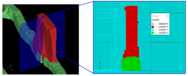
The Block Model Depletion method forces the physical geological to be altered to attribute data within mine workings, adding the benefit of non-void contaminants also being modelled during the evaluation (e.g. cemented fill). In order to recognize a mined block the UGDEP field is used. This field must be assigned a numeric integer code, which will be used by the system during evaluation procedures. By default, the system uses a value of zero to represent material which will be mined and 1 to represent voids. Any other code which is assigned to the M4DDEP field, can be mapped to another material code for depletion purposes.
Warning: Block model size can be significantly affected by this process and care must be taken to ensure that the best combination of parameters and setting is used to optimize both evaluation time and accuracy.
Alternatively, you can choose the Wireframe Boolean method. This doesn't update the model but instead automatically constructs wireframe volumes that represent the remaining in situ volume after mined volumes have been removed. This calculation is performed during processing, and in some cases, can be more accurate
Block Model Depletion Method
The sequence of events performed during block model depletion is summarized as follows:
- A check is made that the specified wireframes are capable of being run against a depletion.
- The selected wireframe data will be treated according to the Type specified in the Depletion Wireframes table. For example, if the Type was set to [Closed Wireframe (Fill Inside)], the wireframe data would be filled accordingly.
- From this solid model, a depletion model is derived. This defines the 'scope' of the depletion.
- Depletion models are appended and optimized as required by the operation.
- The depletion block model is added to the input block model.
- The output block model is optimized.
Wireframe Boolean Depletion Method
If you evaluate volumes using depleted wireframe volumes instead of a depletion-flagged model, the following happens during processing:
- Depletion solids are constructed for the selected design data.
- An evaluation volume is generated that represent the hull of the input planning model.
- Mined void volumes are extracted from the evaluation volume to form a depleted volume.
- The planning model is evaluated against the depleted volume.
Importing and Exporting Data
You can import and export data on panels like this one using the following buttons:
 Import XML data containing settings information
for this task
Import XML data containing settings information
for this task
 Export the currently defined data
Data is stored in XML format and can be transferred to other UG projects and systems, for example.
Depleting a Block Model
To define a block model for depletion:
- Specify an Input block model. This is the block model to be depleted by either flagging void volumes in the model (Block Model Depletion method) or automatically constructing a depleted wireframe volume (Wireframe Boolean method). See Geological Interrogation.
- Specify a Density Column, a block model field that represents material density.
- Specify an Output model file name. This will store depleted block model data.
To define wireframe volumes to perform depletion:
- Click "+" and select a wireframe file representing a depletion volume.
- If required, select a Filter to exclude certain areas from the wireframe file that will be used during the depletion process. See Edit Filters.
-
There are different ways to define the depletion zone for the wireframe file. This is determined by the depletion wireframe Type:
-
Closed Wireframe (Fill Inside) – Cells will be depleted where they fall within the geometry of the selected solid.
-
Closed Wireframe (Fill Outside) – Where the wireframe itself represents the 'no depletion' zone and block model data fall outside will be interrogated for depletion purposes.
-
Surface (Fill Above) – Cells that fall above the wireframe will be deleted.
-
Surface (Fill Below) – Cells that fall below the wireframe will be deleted.
-
Surface (Fill Between) – If there are multiple surfaces this option depletes the area in between.
-
Surface (Fill Outside) – If there are multiple surfaces this option depletes the area outside.
-
-
Choose whether to run a simple or advanced depletion using Method:
-
Basic – For this mode the UGDEP value will be set to 1 for all depletion cells, and when these tonnages are evaluated, depletion cells will not be included in the results. The Settings column is disabled and the New Density column is enabled, allowing you to set the density value for all zones of the wireframe as part of depletion.
If you need more precise control over which zones affect density values, you can use the Advanced method.
-
Advanced – Selecting this mode will activate the Settings column.
-
Click the browse button on the Settings column to open the Advanced Depletion Settings screen
-
Select a custom field and value from which to set up your own depletion rules.
Note: A maximum of 50 unique values are supported.
-
All unique numeric values of the selected Zone Column are listed in the Zone field of the table below.
-
For each listed Zone, selecting Deplete will treat that zone as a void and enable the UGDEP column with the default value (1, representing voids). It is possible to change the UGDEP value to any other than 0.
-
If required, set the density value as part of depletion (New Density).
-
Click OK to return to the Deplete Block Model screen and continue defining depletion settings.
-
-
-
Choose the values to be updated during model depletion using the Update Values commands. This grid contains a list of available fields to be interrogated for the purposes of potential depletion. For each field to be updated:
- Select Update.
-
Enter a New Value to be applied during depletion.
-
Choose other depletion Options:
-
Choose to Delete non zero depletion blocks from output model or not.
-
If checked, model blocks within the depletion model that are found to have a non-zero value will be removed from the output block model.
- If unchecked, a value of zero is used to represent material which will be mined and 1 to represent voids. Any other code which is assigned to the UGDEP field, can be mapped to another material code for depletion purposes.
-
- Choose to Clear existing depletion values before processing or not:
- If checked, the UGDEP field will be cleared before starting the process and filled according to the defined depletion rules.
- If unchecked, the UGDEP field will not be cleared before starting processing. Data values will be overwritten as necessary.
-
- Click Deplete to start the depletion process and generate the depleted model.
- Review the Output panel for progress updates.
The Process output table can provide 3 different levels of information; errors, warnings and messages.- Errors need to be reviewed and resolved before you continue,
- Warnings are highlights showing where elements of your output are unusual but could still be subject to scheduling.
- Messages are status updates that indicate successful processing.
Related Topics and Activities