
Tutorial – Analysis
After mapping structures on your model, you can create analysis sets to further filter your data and assess the stability of any wedges that form. For these activities, use the 3D_Image_demo_with_structures.svpm file provided with Sirovision. The project file is located in the 3D_Model_Demo directory, which is in the same directory as the data used in the previous activities.
Activities
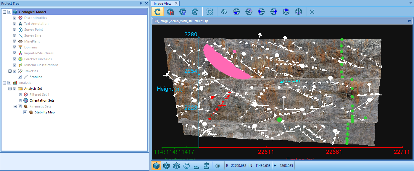
1. Open the 3D_Image_demo_with_structures.svpm model from your default Sirovision directory. Take a moment to familiarise yourself with the mapped structures in this model. The white structures represent planes and traces, and the green structures represent survey points and survey lines.
2. Create an Analysis Set – Before any further analysis, you need to create an analysis set containing all of the planes and traces you want to analyse. For this tutorial, include all of the mapped structures in the analysis set. However, it is important to note that you can filter your mapped structures to create an analysis set with specific structures in future projects. See Create a Filtered Analysis Set.
3. Create Orientation Sets – Orientation sets allow you to group structures within an orientation range together to be analysed. You can manually define each orientation set, or have orientation sets created automatically. For this tutorial, use the Create Orientation Sets option, which automatically classifies structures into groups. Use the default options to create orientation sets.
Note: If the buttons on the Analysis Menu are not enabled, ensure that the Analysis Set is selected in the Project Tree.
By using the default settings of three orientation sets, removal of outliers and a maximum of 20 degrees, Sirovision attempts to create three orientation sets, with a maximum of 20 degrees between the orientation of discontinuities. Any discontinuities that fall out of this range are not included in an orientation set.
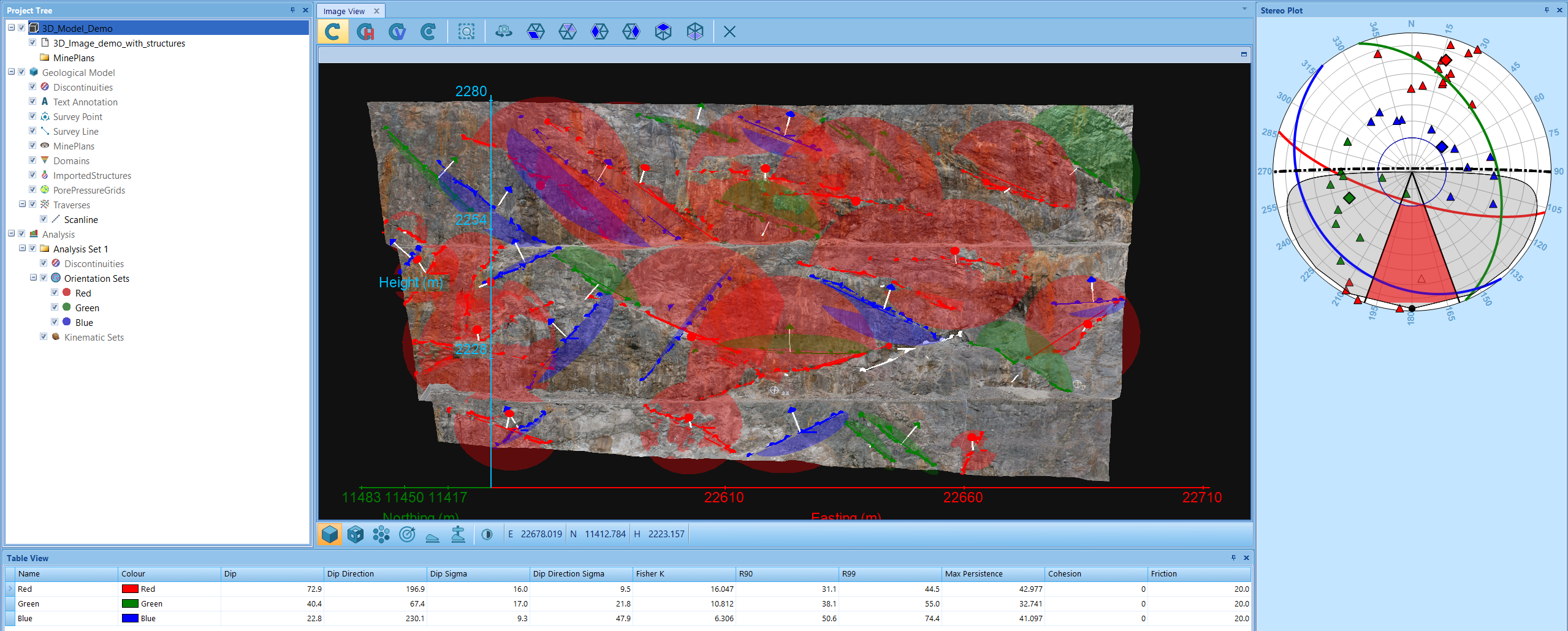
The easiest way to visualise the orientation of the structures on your model is with the Stereo Plot Tab. Each orientation set that was created displays a under the Orientation Sets section in the Project Tree as a distinct colour by default. The colour and name of the orientation sets can be edited in the Table View Panel. When using your own data, even if you choose to create three orientation sets, you may see less, depending on the distribution of your data. If all of the points on your stereonet are clustered in the same place, they will be grouped into the same orientation set.
The example below shows the model with three orientation sets, each represented by a different colour on both the stereonet and the model. The blue, green and red lines on the stereonet each represent the average orientation (dip and dip direction) of the relevant orientation set.
4. Run a Wedge Stability Analysis – Sirovision performs a stability analysis based on either two intersecting discontinuities that form a wedge, or with more sophisticated detection of polyhedral blocks formed from multiple intersecting discontinuities. A wedge or polyhedral block undergoes a limiting equilibrium analysis to determine if it has the potential to slide, given the user-defined friction, cohesion and pore pressure data.
Perform a tetrahedral wedge analysis between two of your orientation sets.
Important: You must have at least two orientation sets to perform a tetrahedral wedge analysis. If you only have one orientation set (that is, only one colour listed under the Orientation Sets section of the Project Tree), add some more planes and traces in different orientations and create the orientation sets again.
After finishing the Stability Analysis Wizard, the Wedge Analysis options displays under Kinematic Sets in the Project Tree. Select Wedge Analysis to view the results of the analysis and assess the stability of any wedges found.
Note: In your own projects, wedges can also be analysed manually on the model using the Plane Intersection tool, or on the stereonet using the Stereonet Plane Intersection tool. See Assess a Stereonet Plane Intersection and Assess a Plane Intersection.