
Map Channel Samples
To access this panel:
-
The Channel Samples panel is part of the Mapping task bar.
Note: The Channel Samples tab will only appear on your system if yoursystem configuration file contains a correctly defined <ChannelSamples>...</ChannelSamples> section.
Channel Samples Overview
The Channel Samples panel contains functions that let you add chip or channel sample data to your maps, either as part of an at-face study, where sample data is collected at the same time as geological feature mapping, or based on previously-harvested field data that is used to enhance a map back at the office. Attributes for channel samples are defined in your system configuration file.
Channel samples can be added to both face and wireframe map types. See Map Types.
A map can contain one or more channel samples.
Note: You can digitize face map data type using either the 3D map or butterfly map view. Butterfly maps are only available if your configuration permits it.
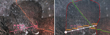
Channel samples will commonly be added after other geological features have been digitized, particularly where channel sample intersection points are important. Commonly, a digital image of the face with channel markup is used for positional guidance and making sure key sample locations are honoured.
Note: Default properties for custom attributes on this panel can be set in your system configuration file.
Rapidly recreate the sample line (or lines) over a digital image or sketch and automatically assign sample IDs based on whatever labelling convention you use. Samples are generated automatically along a new channel, according to your channel sample settings. You can set a target sample length and how samples are position at the junction of neighboring geological structures.
Attributes (shown in the table grid below the functional buttons, and configured in your system configuration file) will either be channel-specific, meaning a single value applies to all samples of the current channel, or sample-specific, meaning a different value can be set for each sample if required. The choice if sample- or channel-specific is defined for each attributed in your configuration file, using the <TargetItem>...</TargetItem> tags.
Tip: If you are using a portable device, automatically display a screen keyboard for easier data entry at the face. Enable screen keyboard mode using the Setup ribbon's On-Screen Keyboard command.
You use the Channel Samples panel to both create the channel and configure the sample positions and values. Tools to inject dummy samples for QA/QC checks are also available.
Note: Channel samples should be fully defined within the same face and, if area grade weighting is required, within the designated face profile.
Smart sample renumbering options are available to make adding and removing samples quick and easy.
Channel samples are defined before any channel sample areas are created, if required for area-weighted grades in downstream processes.
Channel samples data can be exported using the Database Export tool.
Sample Naming Convention
Samples are named according to a preset naming convention comprising a Prefix and Suffix component. The suffix will always contain the number of characters set in your system configuration file (<MinDigits>...</MinDigits>).
-
The Prefix can be numeric or alphanumeric.
-
The suffix (represented by Next) can only be numeric.
A naming convention will be applied for all new channel and validated/regenerated samples. The Prefix will be followed by Next.
Next is automatically increased after adding new samples to be one higher than the highest value in the current map. Duplicate sample IDs are not permitted.
Tip :Format samples to show
the SAMPLE attribute, aligned to the right or left of segment
centre of each sample (showing a perpendicular alignment can
be useful too). You may find a Horizontal offset (with a Vertical
offset of zero) works well, e.g.: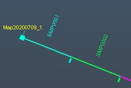
This can be part of a 3D display template, or configured manually
using the Labels tab of the Drillhole Properties screen.
Channel Samples Visual Formatting
Channel samples can be automatically formatted using a display template, or temporarily edited using the 3D properties dialog associated with the channel samples object.
Typical Sampling Workflow
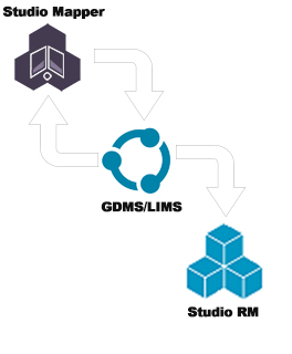
- Studio Mapper's sampling functionality is used to create samples with partially complete information. This data is uploaded to a sample database, usually managed within and by a Geological Data Management System (GDMS) such as DHLogger, prior to samples being chemically assayed.
- Standard samples are added in Studio Mapper to check the laboratory and assaying processes being used. Standard samples are taken from a batch of certified reference material, so their assay values are known. The laboratory values can be checked against the certified values to validate the laboratory's accuracy, as part of a corporate QA/QC process.
- QAQC analysis is in the realm of the GDMS / LIMS being used to store and manage the samples. Mapper provides the non-assayed samples (including standard and duplicate samples) and their locations, which are uploaded to the GDMS.
- Assayed samples are output from the GDMS for use in Studio RM (or other programs used for grade estimation). Channel samples should ideally be output from GDMS systems as
- Desurveyed holes for use in RM or a selection of collars, surveys and downhole tables.
- Assayed samples, if available, can also be loaded into Studio Mapper to further enhance a field report.
The Samples Grid
Tip: If you are using a portable device, automatically display a screen keyboard for easier data entry at the face. Enable screen keyboard mode using the Setup ribbon's On-Screen Keyboard command.
Each channel contains at least one sample. Samples are represented for the currently selected channel using a table of values. Only samples relevant to the selected channel are displayed, and only channels belonging to the currently active map can be selected.
On selecting a new channel, table data is automatically updated.
The table contains a mixture of system and user-defined attributes. The system attributes are:
-
Show/hide check box: toggles the visibility of the sample in the Map and/or 3D World view (if georeferenced).
-
QA/QC: Set a sample as a quality control sample (duplicate, standard, and so on). See Configure QA/QC Samples.
-
SampleID: this will contain an identification label for a sample. Initially generated based on the currently set Prefix and Next values, you can edit these sample properties if you wish. However, any user-defined names will be reverted if you choose to validate the corresponding channel (where default naming will then be reapplied).
These IDs must be unique and this is enforced. If you attempt to rename a sample so that a duplicate ID would occur, the next available SampleID in sequence is applied instead.
-
From/To/Length/Length_CM: editable fields indicating the start and stop positions of the sample and its overall length. Adjusting these values may impact the values for other samples on the channel, for example, if editing a Length or Length_CM causes the sample to accommodate part of the next sample, or subsequent samples for larger intervals. The channel data table will be updated automatically as values are adjusted.
Numeric values must be greater than zero, and each FROM value must be lower than its corresponding TO value.
Any LENGTH values less than the specified Min. length (Channel Sample Settings) will be highlighted in red. These values are normally the result of interactive editing after the channel has been generated.
-
[Custom attributes]: these are set up using your system configuration file and can be either text, numeric or drop-down menu options, with optional field validation. This includes both assay and non-assay attribute types. In the image above, the Rock Type and Comment fields are user-defined.
-
[Assay attributes]: if configured, assays values can be recorded/displayed based on information from your Geological Database Management System (e.g. Datamine Fusion). These attributes are only displayed if the Assays check box is enabled.
-
Face: For face map types only, this indicates the face associated with the channel sample.
Note: This attribute still appears for other map types, but isn't used.
-
Deletex: Delete the selected sample from the channel, rearranging the remaining channels to ensure gaps don't appear. Each channel must have at least one sample.
Select Channel Samples
Channel sample data selection relies on drillhole selection being enabled (it is enabled by default, if drillhole data is loaded). You can enable/disable string selection using the Format ribbon's Select drop-down menu.
If you select one or more channels samples in the Map or 3D world view (you can use <SHIFT> and <CTRL> to pick multiple samples), the corresponding data object will be selected automatically in the Mapping Task Bar. The corresponding table row will also be highlighted.
Conversely, if you select one
or more channel sample table rows, it/they will be highlighted, as
will the corresponding sample(s) in the Map or 3D view.
Activities
To define channel sample settings:
Before you add a channel, you need to define how the samples will be positioned. This is done using the Channel Settings tool:
![]()
- Select a Map and Face.
- Select the Channel Samples tab
- Open the Channel Settings dialog and define values for the options provided.
- Click OK.
- Create your channel using New Channel (see below) or apply the settings to an existing channel by selecting it in the Channel drop-down list and select Validate and Generate Samples.
See Define Channel Sample Settings.
To add a new channel to the active face:
- Select a Map and Face.
- Using the Mapping task bar, select the Channel Samples tab.
- Define your Channel Sample Settings, if not done already.
- Either using the Draw (Channels)
ribbon or the Mapping Task Bar,
select New Channel:

- Digitize two points representing the start and end of the channel.
- A channel will be added with samples automatically dispersed
to match the Target Length
and intersection point settings (Min.
Length, Break before
and Break After).
The channel will be named automatically, either according to the <Name></Name> element of your configuration file followed by a unique suffix, or the map name followed by a unique suffix if no suitable configuration file data can be detected. You can also define your own Prefix if you wish, and set the number that comes Next. - The newly-created channel sample will be automatically selected
(it will appear in the Channel
field).
- The channel table will be updated to display a record for each independent sample.
If you need to remove a sample, you can select the relevant Channel and, within the channel sample table, locate the sample within that channel that needs to be removed.
Then, click the corresponding x button.
Tip: Select a table row to highlight the sample in all 3D windows, or select one in any 3D window to highlight the corresponding table row.
To insert and remove channel samples:
You can add or remove channel sample points using the Insert Point and Delete Point buttons.
These are available in the Mapping Task Bar (Channel Samples tab) and the Draw (Channels) ribbon:
Adding Samples
![]()
Adding a sample will create a new sample entry in the Map or 3D window, and a corresponding table row in the samples table.
The sample will be labelled according to the sample naming values above, ensuring duplicate Sample IDs are not generated by increasing the highest current sample number by one. This may also update the field containing numeric component of the sample ID to show the Next sample ID to be added.
Samples will be added to the currently selected channel only.
Deleting Samples
![]()
Select the Delete Point button, the click on one or more sample positions in the current channel to remove them
Deleting a sample will remove it from the Map or 3D window view and also the samples table. Other samples will not be renumbered as a result.
The first and last sample positions (indicating the start and end of the channel) cannot be removed.
To rename channel samples:
When a channel sample is added to a map, it will have a unique name based on your current configuration file contents. For example, you may have chosen to create a name based on the current map, mine and area names, e.g. "MyMap_FogCreek_220SW_1" where the trailing "_1" is an example of an index, added for uniqueness.
Providing all channel samples on a map face have a unique name, you can rename any channel sample to whatever you like.
To rename a channel sample, you simply edit the name that appears
in the Channel drop-down list, e.g.: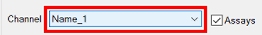
You will be warned if you attempt to name the channel to one that already
exists, and will need to choose a different name.
To edit existing channel sample data:
There are two tools available for dynamically editing channel samples in either a 3D or Map view. These tools are available on the Mapping Task Bar and, when displayed, the Channels | Draw ribbon:

The Move Channel Location function is used to change the location and/or rotation of a channel sample. Any channel sample can be moved (the one nearest the cursor will be modifed). Once this command is active, you can do any of the following to any sample currently in view:- Reposition the cursor without adjusting its rotation: to do this, click anywhere along the sample that isn't the start or the end. Left-click or tap your finger/stylus and drag the sample to the new location. Releasing the mouse button or lifting the finger/stylus from the screen
- Adjust the rotation of the channel: this is achieved by left-clicking and dragging either the start of end of a channel sample and rotating it (using the other end of the sample as the pivot).
Press Done to exit editing mode.

The Edit Channel Sample Locations function lets you modify individual channels on the active map. Even if no channel is selected, clicking onto a channel after selecting Edit Channel will automatically activate the target channel, providing that channel is part of the active map (if you need to edit a channel on another map, you will need to select it first).
This tool is used to used to adjust the limits of each channel sample independently, updating the channel sample table as edits are made.
Note: Once a sample has been edited, it is 'locked', meaning its position will not change if the channel is subsequently validated. Locked sample limits will be lost if the corresponding sample is deleted, or the channel is deleted.
Tip: Configure your database so that the display template used to draw channel sample data clearly displays sample ticks. This makes it easy to see where each sample lies along the channel.
Click any sample FROM or TO position to adjust it and its neighbour. You won't be able to make the sample shorter than the specified Min. Length, nor can you adjust the positions of other intercept markers. Essentially, you can drag the sample limit anywhere between neighboring FROM/TO positions. Only the active Channel or Sample can be edited.
Editing sample FROM/TO positions using the channel sample grid:
As well as interactive repositioning of FROM/TO positions (see above), you can also explicitly set the FROM, TO and LENGTH values in the channel samples table grid.
Setting these values will override existing channel sample settings. In other words, you can create a channel below the Min. Length. Essentially, table data edits are performed regardless of any previous constraints.
- All FROM, TO or LENGTH values must be numeric and greater than 0 (otherwise the previous value is reinstated).
- If FROM, TO or LENGTH edits extend the sample into the subsequent or previous sample, the corresponding FROM, TO and LENGTH of the next or previous sample will be adjusted.
- If edits remove a subsequent or previous sample (say, a new LENGTH completely accommodates the next sample along the channel), affect channels will be removed from the table and values for new neighboring samples calculated.
- You can't adjust the initial (zero) FROM value.
- You cannot make FROM values less than TO.
- You cannot create negative LENGTH values.
- If the final channel sample is extended, the overall channel length is increased to accommodate the final LENGTH.
- If, as a result of table editing, channel sample validation settings are violated, the values will be still be accepted but will be highlighted in red.
Subsequent validation will not adjust the sample limits of adjusted samples, but new sample limits may be added to honour the Target Length.
To add QA/QC samples to a channel:
You can add standard and duplicate samples to any channel, using the QAQC table column's drop-down list.
-
Select the map, face and channel required
-
Click inside the QAQC column for any table row that has no QAQC value
-
Expand the drop-down list and choose either [Add duplicate] (if no duplicate already exists, otherwise this option is hidden) or a standard sample item. The standard sample items in this list are configured by your system configuration file.
To validate and generate channel data:
Samples can be validated/regenerated by selecting the channel and choosing Validate and generate samples. This will apply your current Channel Sample settings to the selected Channel, regenerating the channel in the process.
![]()
For more information on channel sample validation, see Sample Validation.
To create a channel samples plot table template:
You can insert a channel samples table into your map report template that will dynamically update to show the contents of the current map. You set the table up once, and Studio Mapper will automatically update the contents of the table in subsequent reports so that only data relevant to the current map is shown.
For example, you may want to show a table of FROM, TO and other channel values underneath a face on your report.
See Inserting a dynamic channel samples table into your reports.
To export channel sample data to a Fusion database:
-
Load the Studio Mapper project containing the data you wish to export.
-
Open the Export map data to external files dialog.
-
Select the Mine and Area that represents the data you wish to export. All maps within the selected mine and area will form a basis for export.
-
Ensure the Channel Samples check box is selected. All other options are ignored.
-
Select the Fusion database check box and click Export.
-
Initial validation checks are the same as for a physical file export; any maps found that don't have an obvious time/date creation property are displayed first, using the Maps missing dates dialog.
-
Enter your database credentials, using the Fusion Import Credentials dialog and click Finish.
-
Your channel sample data will be translated into a format that your Fusion database will understand. This is all done courtesy of a field mapping template, set up and referenced (normally as part of initial implementation) in your system configuration file.
-
Check system messages and the Output control bar for more information on the export results.