|
|
Merging the Pit and Topography DTMs Combining the pit and topography |

Overview
In this part of the tutorial you are going to merge the pit and topographic DTMs.
Prerequisites
Required:
-
Created a new project and added all the required tutorial files i.e. the exercises on the Creating a New Project page.
Recommended:
-
Specified project and mine design settings i.e. the exercises on the Specifying Design Settings page.
-
Generated a pit DTM i.e. the exercises on the Generating a Pit DTM page.
Files required for the exercises on this page:
-
_vb_stopopt / _vb_stopotr
-
_vb_trc_pit240pt / _vb_trc_pit240tr
Link to Exercises
The following exercises are available on this page:
Exercise: Merging the Pit and Topography DTMs
In this exercise you are going to use boolean commands to generate a merged pit and topography wireframe surface using the _vb_trc_pit240tr/_vb_trc_pit240pt and _vb_stopotr/_vb_stopopt wirerframe objects .This includes the following tasks:
-
Defining data and view settings
-
Merging the pit and topography DTMs
-
Saving the merged wireframe object to a Datamine File.
Defining Data and View Settings
-
Select the Design window.
-
Select the Project Files control bar, Wireframe Triangles folder.
-
Select, drag-and-drop the following files into the Design window:
-
_vb_stopotr
-
_vb_trc_pit240tr
-
-
In the Sheets control bar, Design Overlays folder, select only the following overlays (i.e. display these overlays):
-
Default Grid
-
_vb_stopotr/_vb_stopopt (wireframe).
-
_vb_trc_pit240tr/_vb_trc_pit240pt (wireframe)
-
-
In the Sheets control bar, Design Overlays folder, right-click _vb_stopotr/_vb_stopopt (wireframe), select Format
-
In the Format Display dialog, Overlays tab, Overlay Format group, Style sub-tab, Display As group, check that Faces is selected, click OK.
-
In the View Control toolbar, click Zoom All Data.
-
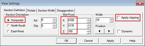
In the View Control toolbar, click View Settings.
-
In the View Settings dialog, define the Section Orientation and Mid-Point XYZ coordinate (6190, 5170, 100) and other parameters shown below, click OK:
-
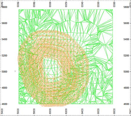
In the Design window, check that your view is as shown below:
Merging the Pit and Topography DTMs
-
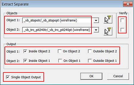
Select Wireframes | Boolean Operations | Extract Separate.
-
In the Extract Separate dialog, select the topography (object 1) and open pit (object 2) wireframe objects.
-
Clear both Verify check boxes.
-
Select the Output group options, check the other highlighted options, click OK:
-
In the Loaded Data control bar, check that the new Extract: _vb_stopotr/_vb_stopopt and _vb_trc_pit240tr/_vb_trc_pit240pt object is listed.
-
In the Sheets control bar, Design Overlays folder, select only the following overlays (i.e. display these overlays):
-
Default Grid
-
Extract: _vb_stopotr/_vb_stopopt and _vb_trc_pit240tr/_vb_trc_pit240pt.
-
-
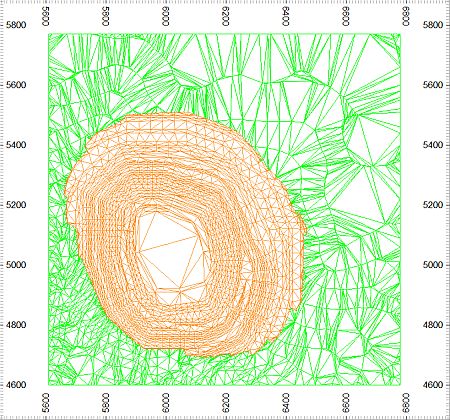
In the Design window, check that your merged wireframe object is as shown below:
-
Select Format | VR View | Update VR Objects (vro).
-
In the VR window, rotate, zoom and pan the view and check that the merged wireframe consists of a green topography surface outside the pit and an orange pit surface inside the topography:
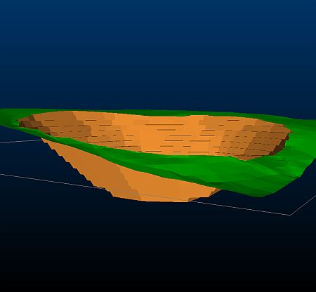
")
In the above wireframe extraction and merging process, the following wireframe surface portions were not retained :
-
pit above the topography
-
topography inside the pit.
When running this command, it may be necessary to run it a number of times before the desired result is obtained.
-
Saving the Merged Wireframe Object to a Datamine File
-
In the Loaded Data control bar, right-click on the Extract: _vb_stopotr/_vb_stopopt and _vb_trc_pit240tr/_vb_trc_pit240pt object, select Data | Save As.
- In the Save New 3D Object dialog, click Single Precision Datamine (.dm) File.
-
In the Save New Strings dialog, select the path to you tutorial folder, define the File name: as 'trc_PitTopotr', click Save.
- In the Loaded Data control bar, check that the Extract: _vb_stopotr/_vb_stopopt and _vb_trc_pit240tr/_vb_trc_pit240pt object has been replaced by trc_PitTopotr/trc_PitTopopt (wireframe).
-
Select File | Save.
Copyright © CAE Inc.
MIN 20048_00_EN