|
|
Adding Crests at the Topography Contours method: adding crests to the toes intersecting the topography surface |
Overview
In this part of the tutorial you are going to add crest strings to the toes which intersect the topography surface.
|
The Contours design method involves inserting ramp and crest strings into an existing set of toe contour strings. These toe strings are typically created by generating contours around an optimum pit shell block mode at the bench toe position. |
Prerequisites
Required:
-
Created a new project and added all the required tutorial files i.e. the exercises on the Creating a New Project page.
-
Loaded and viewed the ultimate pit shell model data i.e. the exercises on the Viewing Ultimate Pit Shell Models page.
-
Created and applied a custom legend, filtered cells, for the NPVS block model i.e. the exercises on the Creating a Custom Display Legend page.
Recommended:
-
Specified project and mine design settings i.e. the exercises on the Specifying Design Settings page.
-
Created ramp design strings i.e. the exercises on the Creating Ramp Strings page.
-
Generated ramp outlines from ramp design strings i.e. the exercises on the Generating Ramp Outlines page.
-
Adjusted toes to ramps i.e. the exercises on the Adjusting Toes to Ramps page.
-
Added crests below the topography surface i.e. the exercises on the Adding Crests Below the Topography page.
-
Adjusted crests to ramps i.e. the exercise on the Adjusting Crests to Ramps page.
Files required for the exercises on this page:
-
_vb_c_pitcrestadj100
-
_vb_stopopt / _vb_stopotr
Link to Exercises
The following exercises are available on this page:
Exercise: Adding Crests At the Topography
In this exercise you are going to use the adjusted crests and ramp design _vb_c_pitcrestadj100 as a starting point for adding crest strings up to 240m elevation. The results will be saved to a new object c_pit240 (strings). This includes the following tasks:
-
Defining data and design plane settings
-
Saving to a new strings file
-
Defining the face projection angle and project to wireframe setting
-
Projecting toes to crest elevations
-
Saving the data.
Defining Data and Design Plane Settings
-
Select the Design window.
-
In the Project Files control bar, Strings folder, drag-and-drop the following file into the Design window:
-
_vb_c_pitcrestadj100
-
-
In the Sheets control bar, Design Overlays folder, select only the following overlays (i.e. display these overlays):
-
Default Grid
-
_vb_c_pitcrestadj100(strings)
-
_vb_stopotr/_vb_stopopt (wireframe)
-
-
In the Sheets control bar, Design Overlays folder, right-click _vb_stopotr/_vb_stopopt (wireframe), select Format.
-
In the Format Display dialog, Overlays tab, Overlay Format group, Style sub-tab, Display As group, select Faces, click Apply.
-
In the Color sub-tab, Color group, select Fixed and the color [(10) Bright Green].
-
In the Line Style group, select the Fixed linestyle [____], and set Width to [1], click OK.
-
In the View Control toolbar, click Zoom All Data.
-
In the View Control toolbar, click View Settings.
-
In the View Settings dialog, define the parameters shown below, click OK:

-
In the View Control toolbar, click Zoom In.
-
In the Design window, drag a zoom rectangle to display the view extents as shown below, so that the toe strings up to the 220m elevation are visible:
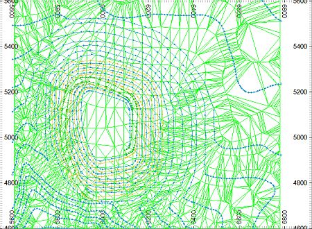

The image above shows the ramp and all toes; the crests are only displayed up to the 80m elevation. This exercise will focus on adding the crest strings up to the 240m elevation.
Saving To a New Strings File
-
In the Loaded Data control bar, right-click on the _vb_c_pitcrestadj100(strings) object, select Data | Save As.
- In the Save New 3D Object dialog, click OK
- In the Save New Strings dialog, select the path to your tutorial folder 'C:/Database/MyTutorials/OPDesign', define the File name: as 'c_pit240.dm', click Save.
- In the Loaded Data control bar, check that _vb_c_pitcrestadj100(strings) has been replaced by c_pit240 (strings).
- Check that c_pit240 (strings) is the current strings object i.e. highlighted bold.
Defining the Face Projection Angle and Project to Wireframe Setting
|
When using the Contours method, generating the crests from the adjusted toes, the default face angle setting needs to be set to the bench face angle, here 60 degrees. |
-
Select Applications | Open Pit | Set Face Angle (fng).
-
In the Studio 3 dialog, check that the default face angle is '60' degrees, click OK.
-
Select Design | Project | Projection to Intersect Wireframe (tiw) to toggle this setting ON.
Projecting the Toes to Topography and Crest Elevations
|
The crests above 100m will be generated by projecting their toes up crest elevation, stopping at the topography wireframe surface where required. In order to make the steps below easier to follow, the images
do not include the topography wireframe BUT, in order for
the Projection to Intersect Wireframe
(tiw) toggle to function, you need to have the _vb_stopotr/_vb_stopopt (wireframe)
overlay displayed. |
-
In the Design window, right-click and select Deselect All Strings (das).
-
Choose Applications | Open Pit | Road Layout Tools | Project String at Angle (pro).
-
In the Studio 3 Project String dialog, define the Projection as 'R' (relative), click OK.
-
In the Studio 3 Project String dialog, define the Projection Distance as '20', click OK.
-
Sequentially select (left-click) at a point on the outside (high side) of each of the 100, 120, 140, 160, 180, 200, 220m elevation toe strings as shown below, click Cancel:
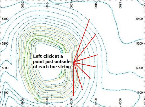

Click OK when 'crossover removal' messages are displayed. In the above image, the wireframe has been hidden in order to make the select points clearer.
-
Select the seven new crest strings using <Ctrl>+Left-click.
-
Select Design | Edit Attributes | Edit (eat).
-
In the Edit Attributes dialog, select a COLOUR attribute value of [4] (yellow), click OK.
-
In the Studio 3 confirmation dialog, click Yes.
-
In the Design window, right-click and select Deselect All Strings (das).
-
Check that your crests are as shown below:
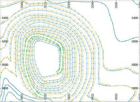

In the above image, the wireframe has been hidden in order to make the strings clearer.
-
Select Format | VR View | Update VR Objects (vro).
-
In the VR window, rotate, pan and zoom the view, noting the position of the new crest strings:
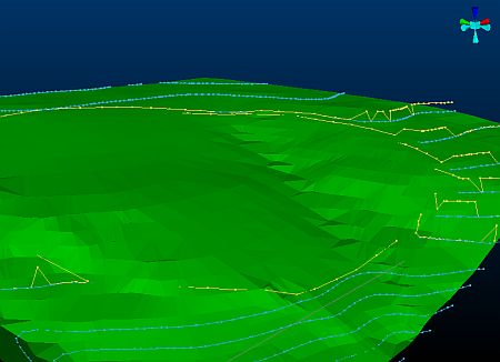

The new crest strings lie above the corresponding toe strings. Note that portions of the projected crest strings extend outside of the pit and above the topography. These portions will be removed.
Removing Unwanted Crest String Portions
-
In the Sheets control bar, Design Overlays folder, hide the following overlay:
-
_vb_stopotr/_vb_stopopt (wireframe)
-
-
In the Design window, zoom in to the south-eastern side of the pit.
-
Select all of the new crest strings.
-
Use Design | String Tools | Break | At Point (bs) and break the strings at the red guide points shown below:
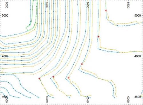

First select the crest string before using the Break String At Selected Point command; this will make it a lot easier to select the correct string for breaking.
-
If not already selected, select the six unwanted eastern portions of these crest strings, as shown (highlighted yellow) below:
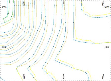
-
Select Edit | Erase | Selected Strings (ers).
-
In the Studio 3 'Do you want to delete the selected String(s)?' confirmation dialog, click Yes.
-
In the Design window, check that the remaining six crest strings are as shown below:
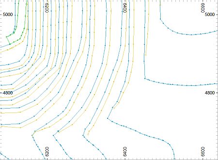
-
In the Design window, zoom in to the north-eastern side of the pit.
-
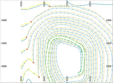
Using the procedure outlined in steps 2 and 3, break the six crest string portions using the red guide points shown below:
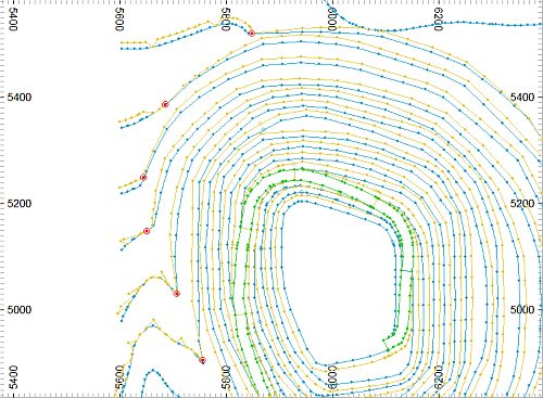
-
Select the six unwanted western portions of these crest strings, as shown (highlighted yellow) below:
-
Select Edit | Erase | Selected Strings (ers).
-
In the Studio 3 'Do you want to delete the selected String(s)?' confirmation dialog, click Yes.
-
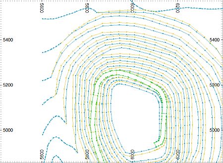
In the Design window, check that the remaining six crest strings are as shown below:
-
Select Format | VR View | Update VR Objects (vro).
-
In the VR window, rotate, pan and zoom the view, noting the position of the six crest strings at the topography surface, relative to their toe strings:
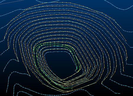

A number of the crest strings do not end at their corresponding blue toe strings. This can be corrected either by extending each string to the relevant point or by selecting alternative crest string breaks points and using other Design tools to modify the remaining string portions.
Saving the Data
-
Select File | Save.
-
In the Save Data/Set Auto Reload dialog, select to Save the c_pit240 (strings) object, click OK.
|
You can check your design strings against the example file _vb_c_pit240 (strings).dm. |
Copyright © CAE Inc.
MIN 20048_00_EN

