
3D Folder - Designed Pit Surfaces
To access this menu:
-
Display the Project Data control bar, expand any 3D window folder and the Designed Pit Surfaces subfolder.
Note: this folder is only displayed if at least one object of the expected type is loaded. Otherwise, this folder will be automatically hidden. 3D folders for independent 3D views are managed using a separate folder arrangement. See Independent 3D Windows.
The Project Data control bar's 3D Designed Pit Surfaces folder is used to display pit shell surface overlays based on pit design shell data that has been loaded from your database (loaded local files never appear in this folder, only database-bound information). These files represent the designed surface of a pit shell at a given date, such as data produced by Studio OP's automated pit design tools, for example.
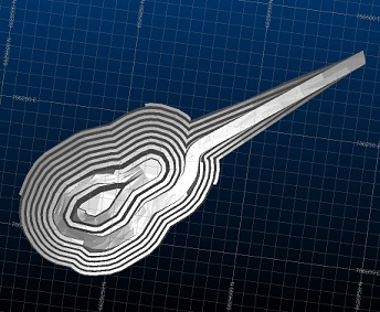
An example of a designed pit surface
This information is used in Compliance to Design reports to assess the volumetric discrepancies between ground data and design data for a given date.
You can load pit design surface data from any date folder, and even load surfaces from multiple dates to for a visual comparison of different design phases.
Designed Pit Surfaces are added to your Survey database using the Add to Database tool. Once added, they will appear in the Survey Database section of the Project Data control bar at the following location:
- Survey Database
- Pits
- [Pit ID]
- Areas
- [Area ID]
- Designed Pit Surfaces
- [year-month-date]
- [File Name]
More about the Project Data control bar's Survey Database folder...
3D objects (loaded file data) can be represented by one or more visual overlays. All overlays are listed here, and are independently configurable. Each item is supported by a context menu providing access to a range of overlay-specific functions as well as object-specific functions. It is important to remember that if you edit the underlying object data in any 3D window (e.g. moving a wireframe vertex, or adjusting a boundary string node), this change will be represented in all overlays associated with that object.
Context Menu Options:
Right-clicking any item within this 3D folder shows the following menu options:
| Save | Open the selected file in the Datamine Table Editor for viewing and editing the file's contents. |
| Data >> | |
| >> Reload | Reload the target data object. See Data Reload. |
| >> Refresh | Refresh the target data object. See Data Refresh. |
| >> Save As | Save the target object to a new file. |
| >> Export | Export the selected data using Datamine's Data Source Drivers facility. |
| >> To Excel | Export the target object and open it using Excel. |
| >> Unload | Unload the target data object. |
| Copy Data From | Append the target object with data from anohter object, using the Select Objects to Copy From screen. |
| Extract | Extract a subset of data from the target object using the Extract Data Object screen. |
| Add Column | Add an attribute to the target object using the Add Column screen. See Add an Attribute to an Object |
| Make Current Object | Make the target object the current object. See Current Objects. |
| Select All | Select all items in the current tree node. |
| Deselect All | Deselect all selected items in the current tree node. |
| Data Object Manager |
Perform object-related functions using the Data Object Manager. |
| Apply Clipping | By default, 3D window clipping will be applied to all object overlays once clipping is activated. You can choose to disable or apply clipping to any overlay independently using this toggle option. View clipping will only be applied to overlays that are 'clipping-enabled'. |
| Link to DTS | Display the Change DTS Column screen to choose the primary key of the DTS schedule. Any numeric column can be used to control the sequence. See Change DTS Column. |
| Rename | Rename the object as it appears in the Project Data bar. This does not change the name of any associated file (if there is one). |
| [Object Name] Properties | Display the properties of the target object. See Item Properties |
| Use Template |
If you have defined one or more 3D display templates for the selected
overlay, you can see them listed here - simply select a template to automatically
update your currently-active
3D window view. This is particularly useful for checking one domain against
another, for example, rock type against a grade. Note: this menu option will only appear if at least one 3D template has been defined for the selected overlay. |
| Copy | Create an identical, automatically named copy of the selected object (note that there is no requirement to paste the item - the list of objects will be updated automatically). Copied objects have no link to their origins; changes to the original object will not affect the duplicated item, and vice versa. |
| Look At | Automatically position the 'camera' to show the selected object. |
| Look at Individual String(strings only) | Display the Select String/Drillhole screen to view a specific string edge. |
| Redraw | Refresh the view of the selected object in the active 3D window. |
| Sequence Controls | If a sequencing attribute has been selected, you can animate playback of the data overlay using sequence values within the selected field. |
| New String (strings only) | Digitize a new string segment within the object associated with the selected overlay. |
| Project to Wireframe/Section (strings only) | Raise or drop all string points onto the nearest wireframe surface. Displays the Project Strings/Points screen. |
| Convert to Planes(strings only) | Convert the target string to a planes object where the plane is established as the best fit plane of all string points. |
| Verify (wireframes only) | Check the loaded Wireframe object for potential data-related problems such as crossovers, empty faces, duplicate faces, duplicate vertices and duplicate edges. Verifying a wireframe object will provide a more consistent data object which will be easier to navigate, texture and manipulate, and is recommended for all new Wireframe data sets. |
| Quick Legend | Create a simple numeric legend using theQuick Legend screen. |
Related topics and activities