
Create Stope Drives
To access this screen:
-
Using the Edit Automated Design Rules screen, select the Create Stope Drives rule and use the browse button in the Settings column.
Generating stope drives, such as cross cuts, can be a laborious part of underground mine design. The Create Stope Drives automated design rule can be used to define the settings that allows design solids to be generated for both longitudinal and transversal drives, typically in relating to existing stope designs such as those output by Mineable Shape Optimizer (MSO).
Stope drives can be designed with respect to the lowest elevation of the stope (floors) and/or the highest elevation (backs). Only stopes of the same level (as indicated by the nominated Level Group and Stope Drive Id column) can be connected. The level can be horizontal or at a constant inclination (inclined levels can be generated in MSO using control strings).
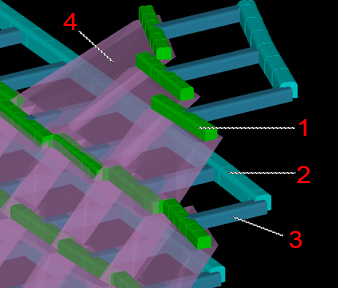
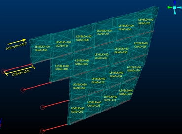
In the image below, the generated stope wireframe design data (4) is connected to the main footwall drive (2) by longitudinal crosscut drives (1) and transversal drives projected (using the shortest distance across the stope through the centre of gravity point) from the longitudinal section to the main drive by an offset distance(3).
Drives are generated in the order indicated by the Stope Drive Sequence Column.
Longitudinal drives are generated using a centerline confined within the stope, located at the center of the stope section and covering the entire stope length. Traversal crosscuts are based on a straight line from the center of the stope section and projecting towards the footwall drive by the specified Offset distance.
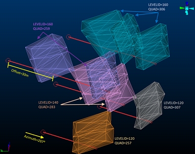
Longitudinal drives are constructed based on the longest centerline path through the stope wireframes (1), with each stope section giving rise to a drives activity at either the floor and/or roof elevation (2)
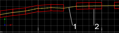
Conversely, traversal drives can be considered the 'shortest path'
(4) from the stope floor at the specified offset distance (4) from
the floor or backs elevation (3) to the footwall drive: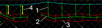
The "longest" and "shortest" path concept may be
clearer to understand using a simple example. In the image below,
a stope section is viewed in plan. The direction used for the longitudinal
drive centerline is shown in orange, whilst the shorter distance,
shown in cyan, is used to project the transversal drives by the nominated
Offset distance. For clarity,
the volumetric center of gravity for the stope section is shown as
a red dot: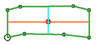
Input Stope Wireframes
Input data is typically that created by Datamine's MSO tool. Stope wireframes generated in this way will automatically contain the attributes required for the Create Stope Drives automated design rule, namely:
- LEVELID distinguishes one or more stopes based on the elevation value of the data. Commonly, this represents the stope floor elevation but this can depend on MSO inputs.
- A unique identifier, for example STOPENUM, that identifies each stope within the set.
- An attribute defining the floor elevation of each stope.
Examples
The following represent typical use cases for the Create Stope Drives automated design rule:
Example 1: Create an Oredrive
For this simple example it is required to create oredrives at each level floor, connecting all stopes and with an entry offset of 30 meters. One option would be to use the LEVELID from MSO as both “Level Group Column” and “Stope Drive Id Column”, because this way all stopes on the same level will be connected with a single string (oredrive). Then, to control which stope connects with which, both QUAD and STOPENUM fields could be used.
Example 2: Creating a Crosscut
For this second example it is required to create crosscuts at each level floor, connecting only stopes “aligned” on the same column (same Tube from MSO). To achieve this one possible solution would be to use the LEVELID as “Level Group Column”, QUAD as “Stope Drive Id Column” since this defines all stopes originated from the same Tube in MSO, and the STOPENUM as the “Stope Drive Sequence” to control which stope connects with each one.
Create a Drive Rule
To configure an automated stope drive creation rule:
-
Select a Wireframe File representing stope shapes.
Note: A stope design wireframe must be specified. The list displays all wireframes design files that have been added to the current planning scenario. See Settings.
- Optionally, pick a Grouping attribute. Data with the same grouping attribute value will be processed independently. This may be useful, for example, to restrict stope drive generation to a particular part of the mine, such as indicated by a STOPEID value, for example.
-
Optionally, define a Filter.
Filters that have been defined for the project are listed. A filter can be specified to focus the scope of crosscut generation, say, to only stopes carrying a particular design definition. If no Filter is specified, an attempt will be made to generate crosscut volumes for all stope data within the input design file. See Edit Filters.
- Define Control Attributes to identify data of distinct levels. All fields are mandatory:
- Define a Level Group attribute. This attribute, normally created during an MSO run, identifies all stopes of a particular level and, subsequently, it will be used to generate longitudinal and transversal crosscut centerlines and volumes on a level-by-level basis.
- Define a Drive Id attribute. This grouping field will be used to isolate all stope sections to be accessed by the same crosscut drive.
- Define a Drive Sequence attribute. This is an attribute in the input design file that identifies the order in which crosscuts will be generated.
-
Specify how stope drive/crosscut centrelines are formed:
- Choose an Elevation attribute:
- Floors - by default, longitudinal and transversal crosscut data will be formed at the floor elevation of each stope level.
- Backs - generate data at the roof elevation
- Both - generate crosscut data at both the floor and roof elevations.
-
Specify the Entry Azimuth for the stope drive data. By default, transversal drives will project from the longitudinal drive at an Azimuth of zero degrees, but you can change this to any angle you need (in a range of 0 to 360).
All transversal drives will project from the center of the stope and at a single, constant azimuth value. This value determines from which side the stope will be entered.
-
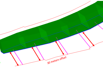
Specify an Offset Distance. This is the distance in the direction of the shortest stope axis (through the centre of gravity) that the transversal drive will be projected, starting at the stope wall. For example, the red arrows below show how the offset distance is applied:
- Choose an Elevation attribute:
- Optionally, define new Filters and Grouping Attributes. See Edit Filters and Edit Groupings.
Related Topics and Activities