
Layers List
The Map Window is organized into layers which can be seen as a stack of transparencies. Each layer contains one Isatis.neo object:
-
 Points,
-
 Polygons,
-
 Polylines,
-
 Grids,
 -
 Raster Maps (geographic raster maps).
When the physical path of the external maps is not accessible or the external map file has been deleted, a red ! (![]() or
or ![]() ) is displayed.
) is displayed.
There is no limit for the number of layers inside a project and you can create your own layers.
Each layer has its own properties and can be activated or deactivated (see below for the list of properties). If several layers are selected, the activation/deactivation will be applied to all the selected layers. The rank of the layer in the stack has its importance and can be changed by dragging and dropping the layers at the desired rank. All layers can be selected using Ctrl+A.
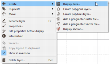
Several actions can be performed on the layer. Use the layer toolbar on the top, or right click on a layer in the Layer List to display the contextual menu:
-
Select
 Create /
  Display data to add and define a new layer.
-
Select
Create /  Create polygons layer to create a new polygon file. A Create Polygon File window will pop up.
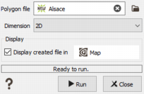
You could then display using the different tools available in the Map Window Tool Bar clicking on Start Editing
 .
. -
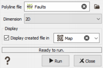
Select
Create /  Create polylines layer to create a new polyline file you could then import using the Vector File Import or digitalize directly from the Map. A Create Polyline File window will pop up.
You could then display using the different tools available in the Map Window Tool Bar clicking on Start Editing
 .
. -
Select Create /
 Add a geographic raster file to load an external raster map. The Import Geographic Raster File will pop up.
-
Select Create /
 Add a geographic vector file to load an external vectorial map. The Import Geographic Vector File will pop up.
-
Select
Create /  Display section to open a Display section window and add a new plane/fence layer. From this panel you can import, copy, rename, export or delete sections. Planes/fences have to be previously stored from a 3D view to be reachable from the dialog window.
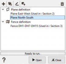
-
Click Import section to pop up the Import section task and import a section definition contained in an xml file.
-
 Click Duplicate to copy the selected section.
-
 Click Rename and enter the new name for the selected section.
-
 Click Export section to pop up the Export section task and export the selected section in an xml file.
-
 Click Delete to definitely remove the selected section(s) from the project.
-
-
Select Duplicate / Duplicate layer to directly duplicate the selected layer with same properties (same point size, same shape, same color (variable), labels active or not...). A new layer xxx 2 will be created.
-
Select
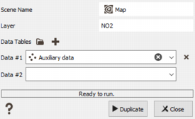
Duplicate / Duplicate layer for data table(s) to duplicate the selected layer but the variable which will be used for the properties can be defined on another data table. When selecting this action, a popup window will present the list of compatible data table(s) to copy to. Select the one(s) you want to base the definition of properties on. The name of the new layer will use the new dataset name and if the variables defined for color, size, ... properties exist, they will be automatically selected in the properties of the new layer.
- Select
 Move /
  Bring to front to put the layer at the top of the stack. Remember that the layer overlay themselves. If several layers are selected, they are all packed and moved at the top of the list, keeping their respective order.
-
Select Move /
 Bring frontward to put the layer in the last rank. If several layers are selected, each one is moved one level upper.
-
Select Move /
 Send backward to bring the layer one rank back. If several layers are selected, each one is moved one level lower.
-
Select Move /
 Send to back to put the layer at the bottom of the stack. If several layers are selected, they are all packed and moved at the bottom of the list, keeping their respective order.
-
Select Rename layer to rename the current layer. Of course, two layers cannot share the same name.
-
Select
 Properties to pop up the Property Window, from this window you can edit the properties of the layers.
-
Select
 Edit properties before display (press Shift when drag and dropping) to activate the creation mode of deactivated layers with the Properties ready to be customized. There is an automatic pop up of the Properties Window for the new layer. Using this mode, all the created layers (with a drag and drop, or using the ’+’ button) are added to the layer list but not displayed (they are unchecked). The properties are easily reachable. This mode is especially useful in case of a big dataset to apply filters. When the button is blue
  the special mode is active. Click again on the button to deactivate the mode.
-
Select
 Information to display layer information (coordinate system, geometry, extension...).
-
Select
 Source to access the File Name of an externalmap (i.e. the location of the physical directory), the associated Encoding and Coordinate System. If the file is a vector image, you can also see the associated layers and attributes. If it is a raster file, you can access the geometry file and save this geometry in a World File.
-
Select
 Copy legend to clipboard to copy in the clipboard the color scale used for the display of the selected variable. This one can then be copied in a Word document for example. This action is only available if a variable has been selected for the Color properties of the layer.
- Select Show in overview to show the layer in the Overview (the Overview is the display below the Layer List).
-
Select
Delete layer to delete the layer, note that you cannot undo this action. If several layers are selected, they are all deleted at once.