
Dynamic Modelling
Dynamic modelling integrates implicit modelling tools to generate a geological model and provide a deeper understanding of what your drillhole data represents.
Dynamic modelling is used for data preparation for production geology modelling or resource modelling. Dynamic modelling lets you configure and manage your model building parameters and logic within a tree structure, which can be shared between users. The tree structure allows for rapid updating of your geological model with new data.
As the Dynamic Modelling environment is a 'container' for a wide selection of other Studio modelling, visualization and data analysis tools, it is referred to as a 'framework' throughout associated help files.
Dynamic modelling uses Boolean tools to combine your contact surfaces, vein models, mineralization shells, and faults into a unified geological model, along with a block model and zoned composites, ready for grade estimation in Studio RM.
Providing seamless access to all of your product's implicit modelling tools, plus other supporting functions such as lithology coding and grouping commands and even macros, how you develop your modelling workflow is up to you.
Typical data used in or generated by dynamic modelling:
-
A prototype model.
Generate a prototype model using PROTOM or its interactive equivalent, create-model-prototype, or you can select any existing block model to use its prototype. The prototype model will be used to constrain the dynamic model.
-
Extents
Constrain output models with a range of boundary options. Multiple boundary options are possible, including topography, bounding prototype model, boundary strings and previously modelled wireframe volumes. See Configure Modelling Extents.
-
Implicit models representing the domain
Contact surfaces represent the structural boundaries of your model, whilst cross-cutting volumes can represent intrusions and vein or reef-like deposits. Categorical and grade shell data represents a wide range of structures. This data, representing the geological domain values that you are modelling, is highly configurable using your product's extensive range of implicit modelling tools. See Configure Domain Task.
-
Faults
Fault sheets can be calculated based on fault trace data (even very sparse information) and you can dynamically adjust fault wireframes in real time. Set up simple or complex fault relationships to ensure output solids and surfaces honour both fully and partly-transecting fault instances. See Model Faults.
-
Block models
Generating a block model representing domain structures is as simple as adding it to the workflow and configuring modelling options using the Dynamic Modelling Properties control bar. See Create a Block Model.
-
Macros
Support your dynamic modelling workflow with additional custom operations provided by macros. This opens up the full process functionality of Studio to your modelling campaign, greatly extending its reach and ensure repeatability and auditability of results. See Integrate Modelling Macros.
See Dynamic Modelling Framework.
Dynamic Modelling Inputs
Dynamic Modelling can include the following inputs
-
Drillholes (static or dynamic) – Typically, Drillhole Importer is used to connect to a drillhole database, but you can also just load prepared drillhole data.
-
Block Model Prototype – To be used as either a way of constraining output data (within the model prototype cuboid) or as a definition for structural block modelling, or both. You can create a prototype automatically based on drillhole data if you like, and adjust its properties using the Dynamic Modelling Properties screen, or just load one that's prepared.
-
Boundary Strings – Set the data extents for modelled data using loaded string data. You can also digitize boundary data.
-
Constraining Wireframes – Closed wireframe volume data can be specified as well. This could be to ensure all modelled data stays within a pit phase, or a stope and so on.
-
Pre-modelled Structures – If you've already modelled important structural data (even using 3rd party applications), you can add it to the workflow and either updated it in line with the latest drilling data or lock it so no further changes occur. Need to extend a Leapfrog implicit model with the latest drilling data? No problem!
-
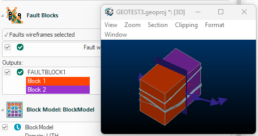
Fault Wireframes – Wireframe surfaces used to denote the fault relationships, for the purpose of creating fault blocks in the output geological model. These wireframes were produced by the Model Faults task.
-
Macros – Customization macros are ideal for fine-tuning your outputs. For example, you may want to add metadata to your output domain models or run a grade-tonnage analysis on the outputs, using a pre-estimated model as an input and dynamically-modelled volumes. There are limitless other applications with the flexible macro framework.
Run All vs. Run Waiting
The Dynamic Modelling framework knows when the data inputs for a result have changed, and when changes don't impact existing results.
For example, changes the input drillhole data will impact a subsequent domain modelling and block modelling task, but may not change the way data boundaries are applied.
Conversely, changes to a domain task item (for example, via the Create Vein Surfaces user interface) will not affect other domain item tasks. In this situation, the former task is set to "Waiting" ( ) and the latter shows as "Complete" (
 )
)
Dynamic Modelling workflow showing both complete and waiting tasks
In essence, a file is set to waiting if anything that changes its inputs or parameters. This includes macro tasks that explicitly reference an item in the Dynamic Modelling workflow.
This means that you can reprocess waiting inputs in isolation by clicking Run Waiting. In this situation, all complete tasks are ignored, meaning the reprocessing is quicker.
You can also override this behaviour by clicking Run All, which reprocesses all tasks regardless of their current status.
Dynamic Modelling Outputs
Dynamic Modelling integrates a range of other tools to generate surfaces and volumes representing the structures within a domain of interest. The outputs from the Dynamic Modelling workflow can include:
-
Vein models
-
Contact surfaces
-
Categorical models
-
Grade shells
-
Fault blocks generated from fault wireframes.
-
A combined domain volume
-
Block models representing implicitly modelled values, either categorical, grade-bound or both.
-
A time vs. volume changes report
The image below shows a combined domain volume comprising implicitly modelled contact surfaces, intrusions and clipped to a topography (not shown). The individual contact surface and volume outputs are also generated and could be analysed separately (say, to evaluation the grade and tonnage of one or both vein intrusions, for example):
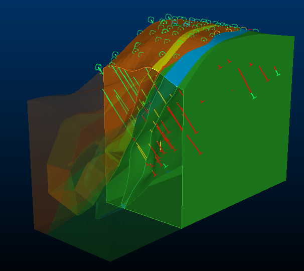
An example of an combined solids wireframe output from Dynamic Modelling
Dynamic Modelling Properties Bar
The Dynamic Modelling framework is supported by a context-sensitive control bar called Dynamic Modelling Properties. Selecting any element of the domain task updates the view to show settings. You can also use this bar to adjust settings, such as the colour of output objects, the display name for workflow elements and so on.
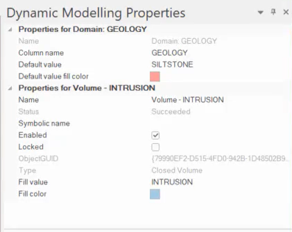
The Dynamic Modelling Properties control bar
See Dynamic Modelling Properties.
Once one or more surfaces or solids have been added to the chronologically-ordered list, select each to decide how material should be categorized within each distinct zone within the model. A zone is formed by the interaction of two or more open wireframe surfaces or one or more closed volumes.
As drilling data becomes available, update your model using the flexible Drillhole Importer to refresh project data, then simply recreate outputs based on the latest field results.
Volume Changes Report
To get a clearer understanding of the impact your modelling decisions have made, each time a combined solid model is generated, volumes of key structures can be stored and visualized, showing you how your parameter decisions have affected the output volumes.
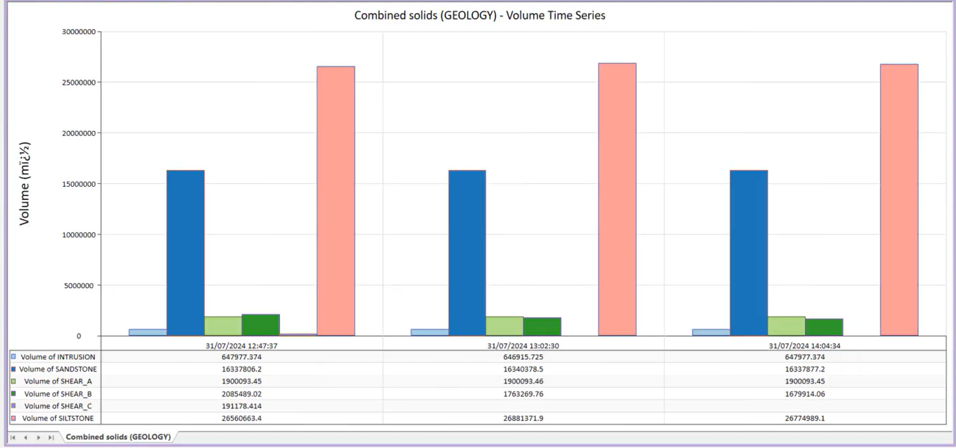
An example of a volume change history report
Dynamic Modelling Workflow
You design your own workflow in Studio Geo, using a many or as few tools as required to finish the job. The workflow is saved and can be used to audit your data modifications throughout the modelling campaign.
As such, each workflow may differ, but as an example, a modelling workflow could involve the following tasks:
-
Create and configure a Studio project, or load one.
-
Load or update loaded drillhole data (say, on a Daily/Weekly basis). Drillhole data updates are easily managed using the Drillhole Importer tool. See Update Drilling Data.
-
Create and manage drillhole coding using grouping and categorization commands.
The Group Lithology and Assign Lithology tasks are designed for this.
-
Launch the Dynamic Modelling task.
-
Design your dynamic modelling workflow. See Define the Workflow.
-
Define a prototype model for implicit model boundary constraint.
-
Specify a topography. See .
-
View and edit contact points from drillholes.
You can easily visualize HW/FW points using the previews available in implicit modelling tools such as Create Contact Surfaces and Create Vein Surfaces tasks.
-
Set your boundary limits and extent of your data. See Configure Modelling Extents.
-
Configure your domain task to determine what surfaces and volumes are generated, and by which tool. See Configure Domain Task.
-
Generate fault data created using the Model Faults task.
-
Generating implicit models by running your workflow tasks. See Process the Workflow.
-
Make edits to your data and recompute outputs. See .
-
Generate a block model representing the modelled domains. See Create a Block Model.
-
Generate a structural model, honouring fault planes. See .
-
Include modelling macros. See Integrate Modelling Macros.
-
Review the output Volume over Time report and see how parameter decisions have affected modelled volume results. See Display Modelling Report.
Also see Define the Workflow.