|
|
Creating a Full Toe-Ramp-Crest Bench Toe-ramp-crest method: creating a complete bench sequence |

Overview
In this part of the tutorial you are going to start with a set of bench strings and create a full bench sequence for a bench i.e. of new toe, ramp and crest strings.
|
The Toe-Ramp-Crest design method (for a bottom-up design direction) makes use of toe, ramp and crest string elements, created in that order, to define a bench in the pit. The full pit design is typically done on a bench by bench basis, starting from the lowest bench and working upwards. For a single bench, the toe string is created and adjusted, the ramp is inserted and finally the crest string are added. This method builds ramps that include access to the berms and can be applied working either from the bottom up or the top down. |
Prerequisites
Required:
-
Created a new project and added all the required tutorial files i.e. the exercises on the Creating a New Project page.
-
Loaded and viewed the ultimate pit shell model data i.e. the exercises on the Viewing Ultimate Pit Shell Models page.
-
Created and applied a custom legend, filtered cells, for the NPVS block model i.e. the exercises on the Creating a Custom Display Legend page.
Recommended:
-
Specified project and mine design settings i.e. the exercises on the Specifying Design Settings page.
Files required for the exercises on this page:
-
_vb_npvmod1
-
_vb_trc_pit-20
Exercise: Creating a Full Toe-Ramp-Crest Bench
In this exercise you are going to use the bench strings _vb_trc_pit-20 as a starting point for creating the next bench (bench 0m) consisting of a full sequence of new toe, ramp and crest strings; it will also be 20m high. This includes the following tasks:
-
Defining data and design plane settings
-
Saving to a new strings file
-
Creating the toe
-
Moving the toe out
-
Adjusting and conditioning the toe string
-
Creating the ramp
-
Creating the crest
-
Saving the data.
Defining Data and Design Plane Settings
-
Unload all data.
-
In the Project Files control bar, All Tables folder, drag-and-drop the following files into the 3D window:
-
_vb_trc_pit-20
-
_vb_npvmod1
-
-
In the Sheets control bar, double-click the Default Section item.
-
Use the Default Section Properties dialog to define the Section Orientation as Horizontal and Mid-Point XYZ coordinate (6110, 5100, -20), then click OK:
-
In the Sheets control bar, Design Overlays folder, select only the following overlays (i.e. display these overlays):
-
Default Grid
-
_vb_trc_pit-20 (strings)
-
_vb_npvmod1 (block model).
")
These settings place the Design view plane (the working plane) at an elevation of -20m i.e. the bottom of bench 0m. This allows the block models cells for bench 0m to be displayed and also used to guide the positioning of the new toe string.
-
-
In the 3D window, drag a zoom rectangle to display the view extents shown below:
Creating the Toe
-
In the 3D window, right-click and select Deselect All Strings (das).
-
In the 3D window, select (left-click) the yellow bench -20 crest string to highlight it.
-
Activate the Design ribbon and select Design | Berm Width.
-
In the Studio OP (Berm Width) dialog, define the Default Berm Width as '8', click OK:

-
Select Design | Berm.
-
Click outside of the yellow perimeter string (anywhere).
-
In the 3D window, right-click and select Deselect All Strings (das).
-
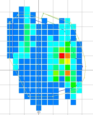
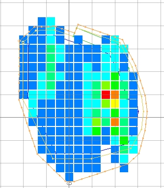
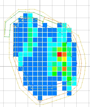
Check that an orange berm (toe) string has been created as shown below, noting the position of the string at the top of the ramp and the block models cells falling outside the toe string in the southern portion of the pit:
Adjusting and Conditioning the Toe String
-
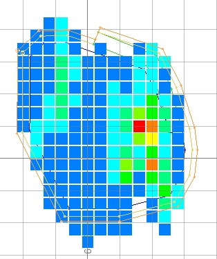
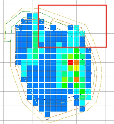
In the 3D window, using Move Points and Insert Points commands, adjust the orange mpotoe string in the southern portion of the pit, outwards to include the ore cells, approximately as shown below:
-
Select the adjusted orange toe string and use the quick key 'cond' to open the Condition String dialog.
-
In the Studio OP (Condition String) dialog, define the settings shown below, click OK:
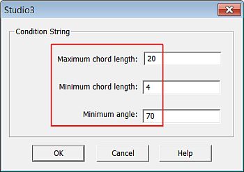
The string will be conditioned so that all chords (segments) are between 4 and 20 metres in length and no internal string angle will be less than 70 degrees.
-
In the 3D window, right-click and select Deselect All Strings (das).
-
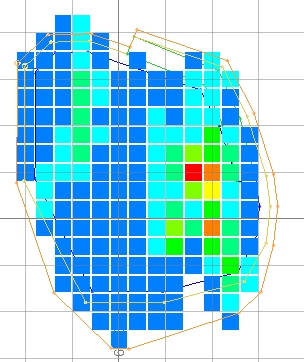
Check that the conditioned toe string is as shown below:
Creating the Ramp
-
In the 3D window, select only the adjusted and conditioned orange toe string to highlight it.
-
Activate the Design ribbon and select Design | Road Segment.
-
In the Studio OP (Road Segment) dialog, define the settings shown below, click OK:
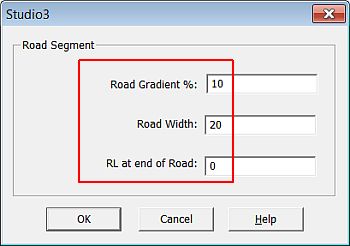
RL at end of road is the elevation at the top of the ramp.
-
As shown below, right-click (snap) to the corner of the toe string where the previous road segment ends and then left-click at a location out towards the north-west:
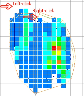
The first point defines the inside corner of the ramp and must be snapped to the toe string; the second point indicates the upwards direction of the ramp i.e. north-west.
-
In the 3D window, right-click and select Deselect All Strings (das).
-
In the 3D window, check that a green ramp string has been created as shown below:
Creating the Crest
-
In the 3D window, select the conditioned orange (-20m elevation) toe string.
-
Using the Design ribbon select Design | Contour
-
In the Studio OP (Create Contour) dialog, define the contour elevation as '0', click OK.
-
In the Design window, right-click and select Deselect All Strings (das).
-
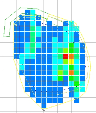
Check that the yellow crest string (perimeter) has been created as shown below:
-
There's a bit of work to do in the north-eastern section of the pit. Select and edit the generated contour string using Insert Points (ipo) until you have something approximately like this:
-
Save your project and click OK.
|
|
If you are not happy with the design at any stage, you can erase the incorrect strings and recreate them using the open pit design commands. The design MUST be restarted from either a toe or crest string, NOT from a road segment. |
|
You can check your design strings against the example file _vb_trc_pit0.dm. |
Copyright © Datamine Corporate Limited
JMN 20048_00_EN