|
|
Designing a Switchback Toe-ramp-crest method: using the complete sequence to create a switchback ramp. |

Overview
In this part of the tutorial you are going to design the upper portion of a switchback road for a bench, consisting of new ramp, enlarged crest flat and new crest strings.
|
The Toe-Ramp-Crest design method (for a bottom-up design direction) makes use of toe, ramp and crest string elements, created in that order, to define a bench in the pit. The full pit design is typically done on a bench by bench basis, starting from the lowest bench and working upwards. For a single bench, the toe string is created and adjusted, the ramp is inserted and finally the crest string are added. This method builds ramps that include access to the berms and can be applied working either from the bottom up or the top down. |
Prerequisites
Required:
-
Created a new project and added all the required tutorial files i.e. the exercises on the Creating a New Project page.
-
Loaded and viewed the ultimate pit shell model data i.e. the exercises on the Viewing Ultimate Pit Shell Models page.
-
Created and applied a custom legend, filtered cells, for the NPVS block model i.e. the exercises on the Creating a Custom Display Legend page.
Recommended:
-
Specified project and mine design settings i.e. the exercises on the Specifying Design Settings page.
Files required for the exercises on this page:
-
_vb_npvmod1
-
_vb_trc_pit70
Exercise: Designing a Switchback
|
|
The procedure for creating a switchback is much the same as that used to create a standard spiral ramp section. The general procedure is as follows:
A switchback can be created at any elevation within the pit. |
In this exercise you are going to use the pit strings _vb_trc_pit70 as a starting point for creating a switchback for the next bench (bench 80m) consisting of a full sequence of new toe, ramp and crest strings; the bench will be 10m high. This includes the following tasks:
-
Defining data and design plane settings
-
Saving to a new strings file
-
Creating the upper switchback ramp
-
Enlarging the 70m crest area
-
Creating the 80m toe
-
Saving the data.
Defining Data and Design Plane Settings
-
Activate the 3D window if not already in view.
-
Unload any previously loaded/created data.
-
In the Project Files control bar, Strings folder, drag-and-drop the following file into the 3D window:
-
_vb_trc_pit70
-
_vb_npvmod1
-
-
In the Sheets control bar, display only the following overlays:
-
Default Grid
-
_vb_trc_pit70 (strings)
-
_vb_npvmod1 (block model)
-
-
Double click Sheets | Sections | Default Section.
-
In the Default Section Properties dialog, define the Section Orientation as Horizontal and Mid-Point XYZ coordinate (6110, 5100, 70). Click OK.
-
Double-click the Sheets | Block Models | _vb_npvmod1 (block model) item.
-
Using the Block Model Properties dialog, set the Column to [PUSHBACK] and choose the default legend for this attribute. Click OK.
-
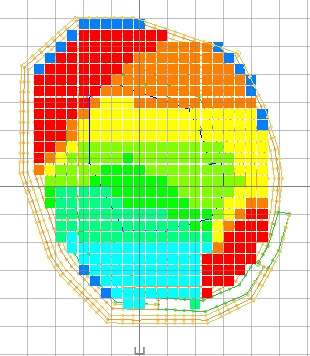
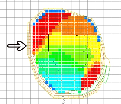
In the 3D window, drag a zoom rectangle to display the view extents shown below:
Saving To a New Strings File
-
In the Loaded Data control bar, right-click on the _vb_trc_pit70 (strings) object, select Data | Save As (you can also use the Sheets control bar to do this)
-
In the Save New 3D Object dialog, click Extended Precision Datamine (.dm) File.
-
In the Save New Strings dialog, select the path to your tutorial folder 'C:/Database/MyTutorials/OPDesign', define the File name: as 'trc_pit80', click Save.
-
In the Loaded Data control bar, check that _vb_trc_pit70(strings) has been replaced by trc_pit80 (strings).
- Check that trc_pit80 (strings) is the current strings object i.e. highlighted bold.
Creating the Upper Switchback Ramp
-
In the 3D window, select the yellow crest string at the top of the design.
-
Using the Design ribbon, select Design | Road Segment.
-
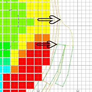
In the Studio OP (Road Segment) dialog, define a Road Gradient % of '10', a Road Width of '20', an RL at end of Road of '80', click OK:
")
RL at end of road is the elevation at the top of the ramp.
-
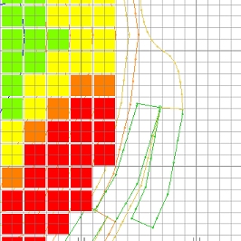
As shown below, right-click (snap) to the outside corner of the yellow crest string where the previous road segment ends and then left-click at a location out towards the south:
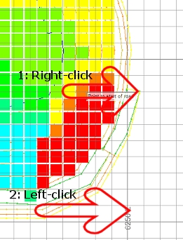
The first point defines the inside corner of the ramp and must be snapped to the indicated crest string; the second point indicates the upwards direction of the ramp i.e. south.
-
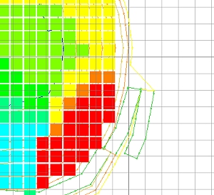
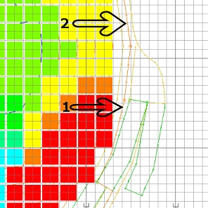
In the Design window, check that a green ramp string has been created and that the crest string has been automatically modified, as shown below:
Enlarging the 70m Crest Area
|
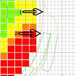
The flat area connecting the two ramps needs to provide enough turning space for machines traveling on the haul roads and is defined by two crest strings as follows:
|
-
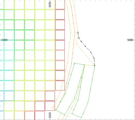
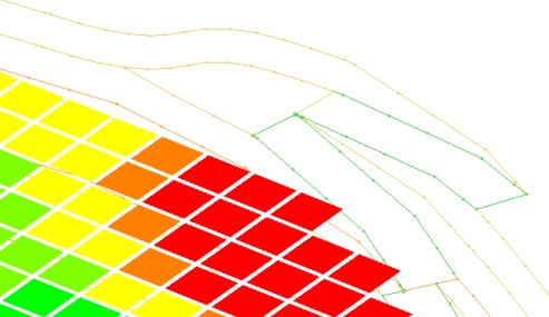
In the 3D window, active the Edit ribbon and use the commands Edit Point and Move Point to adjust the yellow 70m crest string between the two ramps, outwards to increase the flat area, as indicated by the black dashed line shown below:
You could also use the Insert-curve command to achieve the same effect - just click two points and define an s-shaped curve e.g.: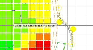
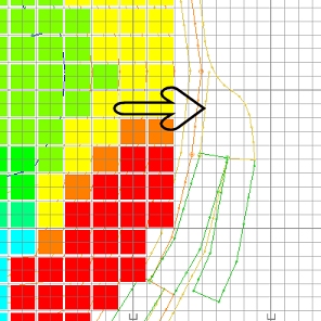
-
Check that you have moved and inserted points, to place the standard yellow crest string in the position shown below:
-
Select the orange 60m toe string. This is the string just inside the outermost yellow crest string that you just modified.
-
Using the Edit ribbon, select Tools | Break and break this string at the two points shown below, starting with the northern point:
-
Select the short portion of broken string (it will become independently highlighted).
-
Using the Design ribbon, select Design | Contour.
-
In the Studio OP (Create Contour) dialog, define the Contour Level as '70', click OK.
-
In the 3D window, right-click and select Deselect All Strings (das).
-
Check that the short yellow crest string (with three segments) has been created as shown below:
-
Select this short crest string and using Move Points (Edit ribbon), move both end points of this short string, snapping them (right-click) onto the points shown below:
If you are unsure of where the end points are positioned, first move them away into the adjacent white space using left-click, then move them back in again, this time snapping (right-click) them to the required final points. Here, the northern point of the short crest string snaps to the enlarged standard crest string; the southern point of the short crest string snaps to the top inside corner of the previous ramp string.
-
Using the Edit ribbon, select Tools | Connect (conn) , following the prompts in the Status Bar, connect the three portions of broken orange 60m toe string shown below:
-
Zoom out, select the connected 60m toe string and check that it is again a single closed string (perimeter), highlighted yellow.
Creating the Bench 80 Crest
-
Select the outer, full standard 70m crest string.
-
Using the Design ribbon, select Design | Contour (rcon).
-
In the Studio OP (Create Contour) dialog, define the Contour Level as '80', click OK.
-
In the 3D window, right-click and select Deselect All Strings (das).
-
Check that a full, yellow 80m crest string has been created as shown below:
The upper ramp of the switchback does not have an orange toe string, but instead uses the crest string which forms part of the lower half ramp.
-
Rotated the view and check check that your new pit benches are as shown below:
Save your project.
|
|
If you are not happy with the design at any stage, you can erase the incorrect strings and recreate them using the open pit design commands. The design MUST be restarted from either a toe or crest string, NOT from a road segment. |
|
You can check your design strings against the example file _vb_trc_pit80.dm. |
Copyright © Datamine Corporate Limited
JMN 20048_00_EN