|
|
Adding Crest Strings Toe-ramp method: adding the crest strings to the toe-ramp design |

Overview
In this part of the tutorial you are going to add crest strings to a toe-ramp pit design.
|
The Toe-Ramp design method involves first creating all the toe and ramp strings and then adding the crest strings. This method is quicker than the Toe-Ramp-Crest approach and yields a continuous ramp with no offsets on the berms. A toe-ramp design sequence starts and ends with a toe string. If you are not happy with the design at any stage, you can erase the incorrect strings and recreate them using the open pit design commands. The design MUST be restarted from toe string, NOT from a road segment. |
Prerequisites
Required:
-
Created a new project and added all the required tutorial files i.e. the exercises on the Creating a New Project page.
-
Loaded and viewed the ultimate pit shell model data i.e. the exercises on the Viewing Ultimate Pit Shell Models page.
-
Created and applied a custom legend, filtered cells, for the NPVS block model i.e. the exercises on the Creating a Custom Display Legend page.
Recommended:
-
Specified project and mine design settings i.e. the exercises on the Specifying Design Settings page.
-
The Toe-Ramp-Crest method exercises.
-
The preceding Toe-Ramp method exercises.
Files required for the exercises on this page:
-
_vb_tr_pit260
Link to Exercises
The following exercises are available on this page:
Exercise: Adding the Crest Strings to the Toe-Ramp Design
In this exercise you are going to use the existing toe-ramp design _vb_tr_pit260 as a starting point to complete the pit design by adding crest strings. The completed pit design will be saved to a new object tr_pitcrests (strings). This includes the following tasks:
-
Defining data and design plane settings
-
Saving to a new strings file
-
Setting the projection angle and crest string color
-
Adding the crests
-
Saving the data.
Defining Data and Design Plane Settings
-
Select the Design window.
-
In the Project Files control bar, Strings folder, drag-and-drop the following file into the Design window:
-
_vb_tr_pit260
-
-
In the Sheets control bar, Design Overlays folder, select only the following overlays (i.e. display these overlays):
-
Default Grid
-
_vb_tr_pit260 (strings)
-
-
In the View Control toolbar, click Zoom All Data.
-
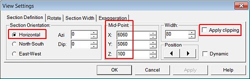
In the View Control toolbar, click View Settings.
-
In the View Settings dialog, define the Section Orientation and Mid-Point XYZ coordinate (6060, 5060, 100) and other parameters shown below, click OK:
-
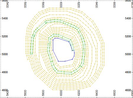
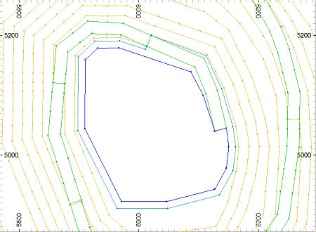
In the Design window, check that your view is a shown below:
")
In the above image the toe-ramp pit design only consists of toe and ramp strings up to ( and not more than a bench above) where the ramp intersects the surface and only toe strings above that elevation. The crest strings will be added to all benches to form a complete, untrimmed (i.e. to the topography surface) pit design.
Saving To a New Strings File
-
In the Loaded Data control bar, right-click on the _vb_tr_pit260 (strings) object, select Data | Save As.
-
In the Save New 3D Object dialog, click OK.
-
In the Save New Strings dialog, select the path to your tutorial folder 'C:/Database/MyTutorials/OPDesign', define the File name: as 'tr_pit260Crests.dm', click Save.
- In the Loaded Data control bar, check that _vb_tr_pit260 (strings) has been replaced by tr_pit260Crests (strings).
Setting the Projection Angle and Crest String Color
|
When using the Toe-Ramp method, creating the ramp and toe strings, the default projection face angle setting needs to be set to the overall pit wall slope and not the slope of a bench face; here the overall pit slope angle is 50 degrees. This angle needs to be set back to the bench face angle (here 60 degrees) when adding the crest strings. |
-
Select Applications | Open Pit | Set Face Angle (fng).
-
In the Studio 3 dialog, define the Projection Face Angle as '60' degrees, click OK.
-
Select Applications | Open Pit | Set Colors | Contour.
-
In the Studio 3 dialog, define the Colour for Crest/Contour Strings as '6', click OK.
Adding the First Crest String
-
In the View Control toolbar, click Zoom In.
-
In the Design window, drag a zoom rectangle to display the view extents shown below:
-
In the Design window, select (left-click) the dark blue toe string of the first bench (-40m elevation).
When creating the crest strings for each bench, you are selecting the reference toe string, NOT the ramp string.
-
In the Pit Design toolbar, click Create Road Contour (rcon).
-
If required, following the prompt in the Status Bar, select a position outside of the selected perimeter (this indicates the high side i.e. the side on which to create the crest string).
-
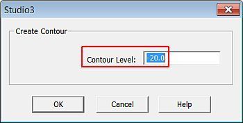
In the Studio 3 (Create Contour) dialog, define the contour elevation as '-20', click OK:
-
In the Design window, right-click and select Deselect All Strings (das).
-
Check that the cyan (color 6) crest string has been created at the -20m elevation as shown below:
Adding the Remaining Crest Strings
-
Using the steps shown in the above section, incrementing the contour level by 20m each time, generate the crest strings for the remaining benches, with the last crest at 240m elevation.
When creating the crest strings for each bench, you are selecting the reference toe string, NOT the ramp string.
-
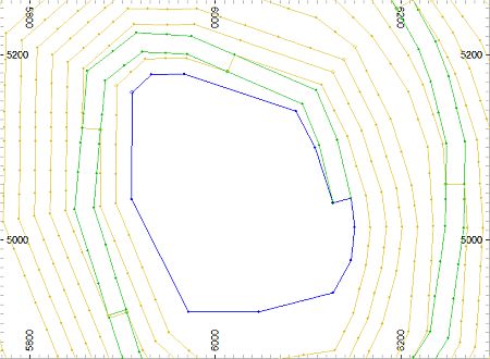
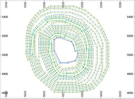
In the Design window, check that the remaining crest strings (0, 20, 40, 60, 80, 100, 120, 160, 140, 180, 200, 220, 240m elevations) have been generated as shown below:
-
Select Format | VR View | Update VR Objects (vro).
-
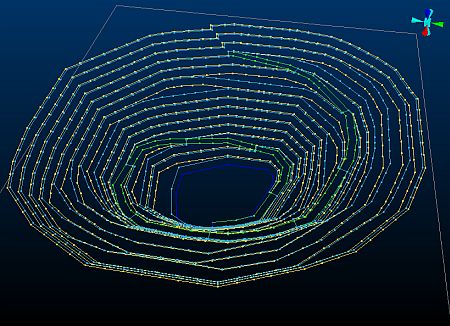
In the VR window, rotate and zoom the view and note that the positions of the crest strings relative to the existing toe and ramp strings, as shown below:
Saving the Data
-
Select File | Save.
-
In the Save Data/Set Auto Reload dialog, select to Save the tr_pit260Crests (strings) object, click OK.
|
You can check your design strings against the example file _vb_tr_pit260Crests.dm. |
Copyright © CAE Inc.
MIN 20048_00_EN