|
|
Designing at the Topography Surface Toe-ramp method: how to design the pit through the topography surface. |

Overview
In this part of the tutorial you are going to design the topmost portion of the toe-ramp open pit where it intersects the topography surface.
|
The Toe-Ramp design method involves first creating all the toe and ramp strings and then adding the crest strings. This method is quicker than the Toe-Ramp-Crest approach and yields a continuous ramp with no offsets on the berms. A toe-ramp design sequence starts and ends with a toe string. If you are not happy with the design at any stage, you can erase the incorrect strings and recreate them using the open pit design commands. The design MUST be restarted from toe string, NOT from a road segment. |
Prerequisites
Required:
-
Created a new project and added all the required tutorial files i.e. the exercises on the Creating a New Project page.
-
Loaded and viewed the ultimate pit shell model data i.e. the exercises on the Viewing Ultimate Pit Shell Models page.
-
Created and applied a custom legend, filtered cells, for the NPVS block model i.e. the exercises on the Creating a Custom Display Legend page.
Recommended:
-
Specified project and mine design settings i.e. the exercises on the Specifying Design Settings page.
-
The Toe-Ramp-Crest method exercises.
-
The preceding Toe-Ramp method exercises.
Files required for the exercises on this page:
-
_vb_npvmod1
-
_vb_tr_pit200
-
_vb_tr_pit260
-
_vb_stopopt / _vb_stopotr
Exercise: Designing Through the Topography Surface
In this exercise you are going to use the pit strings _vb_tr_pit200 as a starting point for designing the toe string for bench 220. In addition, you will view the completed example toe strings up to 240m elevation. This includes the following tasks:
Defining data and design plane settings
Saving to a new strings file
Creating the bench 220 toe string
Adjusting the bench 220 toe string
Saving the data
Viewing the toe strings up to bench 240.
Defining Data and Design Plane Settings
Activate the 3D window.
Unload-all-data (ua)
In the Project Files control bar, Strings folder, drag-and-drop the following file into the 3D window:
_vb_tr_pit200
_vb_tr_pit260
_vb_stopotr/_vb_stopopt
_vb_npvmod1
In the Sheets control bar display only the following overlays:
Default Grid
_vb_tr_pit200 (strings)
_vb_stopotr/_vb_stopopt (wireframe)
_vb_npvmod1 (block model)
Using the same technique as previous tutorials, change the block model overlay so that is coloured according to the default legend for PUSHBACK.
In the Sheets control bar, double-click _vb_stopotr/_vb_stopopt (wireframe)
In the Wireframe Properties dialog, Overlays tab, Display As group, select Intersection.
In the Intersection Section drop-down list, select [Default Section]
Select the Fixed color [(10) Bright Green] and click OK.
In the Sheets control bar, double-click the Default Section item.
Use the Default Section Properties dialog to define the Section Orientation as Horizontal and Mid-Point XYZ coordinate (6070, 5050, 180)
Set the Section Width to '40' for the Front and '40' for the Back.
In the Clipping section, select Outside to display only data within the section limits.
")
These settings place the 3D activesection at an elevation of 180m i.e. the toe elevation for bench 200.
The clipping option is used to display only the data which falls within 40m above or below the selected view plane. It makes it possible to view the full two previous benches and the new bench design strings.
In the 3D window, drag a zoom rectangle to display the view extents shown below:
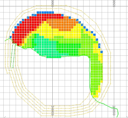
In the above image the green intersection line, cutting through the pit with a northwest-southeast orientation, is the 180m contour for the topography surface. This line is at the same elevation as the top of bench 180, which consists of a full set of toe and ramp strings. This is the first bench ramp to extend beyond the topography surface. From this elevation onwards no more ramp strings are required.
Saving To a New Strings File
In the Sheets control bar, right-click on the _vb_tr_pit200 (strings) object, select Data | Save As.
- In the Save New 3D Object dialog, click Extended Precision Datamine (.dm) File.
- In the Save New Strings dialog, select the path to your tutorial folder 'C:/Database/MyTutorials/OPDesign', define the File name: as 'tr_pit220.dm', click Save.
- In the Loaded Data control bar, check that _vb_tr_pit200(strings) has been replaced by tr_pit220 (strings).
Creating the Bench 220 Toe String
As the bench 180 ramp now extends beyond the topography surface, no more ramp strings are required for the design. The bench 200 toe string has already been created and does not require a ramp string. From here onwards, only toe strings need to be created for each bench. In the following section the bench string for bench 220 will be generated and adjusted. |
Using the Design ribbon select Design | Face Angle (fng).
In the Studio OP dialog, check that the default face angle is '50' degrees, click OK.
Check that tr_pit220 (strings) is the current strings object i.e. highlighted bold.
Activate the View ribbon and select Sections | Move (mpl).
In the Studio OP dialog, define the Distance to move plane as '20', click OK.
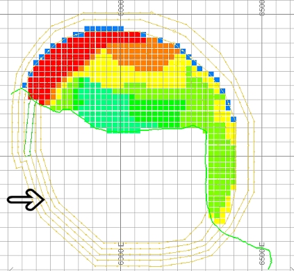
In the 3D window, select the yellow 180m elevation toe string. This is the middle of the 5 displayed toes strings as indicated below:
Using the Design ribbon, select Design | Contour.
In the Studio OP (Create Contour) dialog, define the contour elevation as '200', click OK.
In the 3D window, right-click and select Deselect All Strings (das).
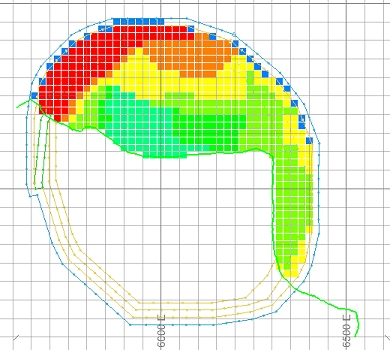
Check that the 200m elevation (bench 220) toe string has been created as shown in blue below:
Use the Section Properties dialog to set Clipping to None. Click OK.
Use the Wireframe Properties dialog to change the Shading to Flat and click OK.
In the 3D window, pan, rotate and zoom the view and note that the additional bench 220 toe string, its relationship to the preceding bench 200 and bench 180 (with ramp) strings and the unclipped topography surface:
Save your project and data.
Viewing the Toe Strings up to Bench 260 (240m elevation)
In the Sheets control bar, enable the display of _vb_tr_pit260 (strings)
Change the display of the topography back to an intersection with the Default Section.
Use the View ribbon's View | Align command to set a plan view.
Zoom-all-data.
Open the Default Section Properties dialog and define the Section Orientation as Horizontal and Mid-Point XYZ coordinates (6070, 5050, 240), make sure Clipping is set to None and click OK:
In the 3D window, drag a zoom rectangle to display the view extents shown below:
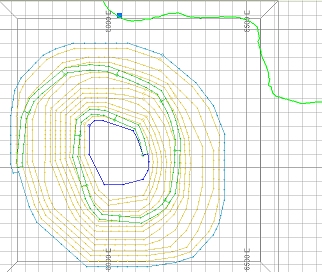
The image above displays the topography wireframe sliced at 240m elevation. The yellow toe strings without associated ramp strings represent benches 260, 240, 200 and 200. Bench 260 toe (240m elevation) lies completely above the the topography surface
Set the topography back to a flat shaded wireframe again.
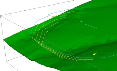
In the 3D window, rotate, pan and zoom the view and note the additional toe strings and their relationship to the topography surface:
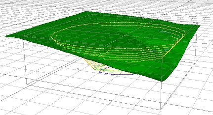
The bench 180 ramp extends just above the topography surface. From here on upwards, the remainder of the pit design only consists of bench toe strings up to a elevation of 240m (toe of bench 260). It is important that the final toe string is generated so that it lies completely above the topography wireframe surface.
Copyright © Datamine Software Limited
JMN 20048_00_EN