|
|
Trimming the Design Strings Trimming the pit design strings against the topography surface |

Overview
In this part of the tutorial you are going to trim the design strings to topography using the pit-topography intersection string.
Prerequisites
Required:
-
Created a new project and added all the required tutorial files i.e. the exercises on the Creating a New Project page.
Recommended:
-
Specified project and mine design settings i.e. the exercises on the Specifying Design Settings page.
-
Generated a pit DTM i.e. the exercises on the Generating a Pit DTM page.
-
Generated a pit-topography intersection string i.e. the exercises on the Generating a Pit-Topo Intersection page.
Files required for the exercises on this page:
-
_vb_trc_pit240
-
_vb_trc_PitTopoInt
-
_vb_stopopt / _vb_stopotr
Link to Exercises
The following exercises are available on this page:
Exercise: Trimming the Design Strings
In this exercise you are going to trim the _vb_trc_pit240 design strings to lie below the topography surface using the _vb_trc_PitTopoInt pit-topography intersection string. This includes the following tasks:
-
Defining data and view settings
-
Generating the intersection
-
Trimming the design strings
-
Saving the trimmed design strings to a new Datamine file.
Defining Data and View Settings
-
Select the Design window.
-
Select the Project Files control bar, Wireframe Triangles folder.
-
Select, drag-and-drop the following files into the Design window:
-
_vb_stopotr
-
-
Select the Project Files control bar, Strings folder.
-
Select, drag-and-drop the following files into the Design window:
-
_vb_trc_pit240
-
_vb_trc_PitTopoInt
-
-
In the Sheets control bar, Design Overlays folder, select only the following overlays (i.e. display these overlays):
-
Default Grid
-
_vb_trc_PitTopoInt (strings)
-
_vb_trc_pit240 (strings)
-
_vb_stopotr/_vb_stopopt (wireframe).
-
-
In the Sheets control bar, Design Overlays folder, right-click _vb_stopotr/_vb_stopopt (wireframe), select Format
-
In the Format Display dialog, Overlays tab, Overlay Format group, Style sub-tab, Display As group, check that Faces is selected, click OK.
-
In the View Control toolbar, click Zoom All Data.
-
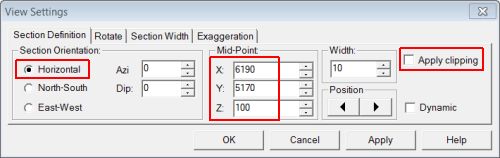
In the View Control toolbar, click View Settings.
-
In the View Settings dialog, define the Section Orientation and Mid-Point XYZ coordinate (6190, 5170, 100) and other parameters shown below, click OK:
-
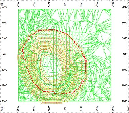
In the Design window, check that your view is as shown below:
Trimming the Design Strings
-
In the Design window, select the red intersection string.
-
Select Design | String Tools | Clip to Perimeter.
-
Following the 'Select a point on the deletion side' prompt displayed in the left side of the Status Bar.
-
In the Design window, click anywhere outside the intersection string, click Cancel.
-
Right-click and select Deselect All Strings (das).
-
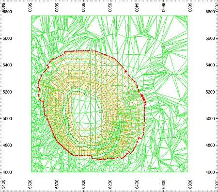
Check that the pit design strings have been trimmed to only lie inside the red intersection string, as shown below:
-
Select Format | VR View | Update VR Objects (vro).
-
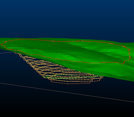
In the VR window, rotate, zoom and pan the view and check that the pit design strings have been trimmed to lie only below the topography surface:
Saving the Trimmed Strings to a New Datamine File
-
In the Loaded Data control bar, right-click on the _vb_trc_pit240 (strings) object, select Data | Save As.
- In the Save New 3D Object dialog, click Single Precision Datamine (.dm) File.
-
In the Save New Strings dialog, select the path to you tutorial folder, define the File name: as 'trc_pit.dm', click Save.
- In the Loaded Data control bar, check that the _vb_trc_pit240 (strings) object has been replaced by trc_pit (strings).
-
Select File | Save.
Copyright © CAE Inc.
MIN 20048_00_EN