
Edit Attributes
To access this screen:
-
Display the Edit Naming Conventions panel without loading data and click Edit Attribute Definitions.
-
Display the Manual Attribute Assignment panel without loading data and click Edit Attribute Definitions.
-
Display the Derived Activities panel and select Edit Attributes.
-
Display the Project Settings toolbar and select Edit Attributes.
Note: Attributes cannot be defined if design data is loaded. It must be unloaded before you can access the Attributes panel. If attribute changes are made in the current project, but the design hasn't changed, the edited or new attributes are placed on the activity when processing next occurs.
Data attributes are used throughout the planning and scheduling process to ensure that information is passed from task to task in an expected way. For example, a LEVELID attribute can help to apply specific processing rules, such as automated layout rules, depending on the which level of the system is being planned.
Attributes are defined using the Attributes panel. Attributes are either user-defined or system (in which case, they are not editable but can be applied to any convention).
Here are some examples of attribution for an underground planning scenario:
- Level – Mine design level information.
-
Zone – Defines different geological zones within the mine or climate zones indicating areas that require greater ventilation.
-
Orebody – Defines the orebody within which a mining segment is located.
-
Support – Indicates which areas of the mine require what level of support.
Almost anything can be added as an attribute. They should increase your understanding of a design, and make the associated schedule more informative. However, excessive use of attributes may create more confusion than clarity.
The main drawback of an attribute is that it cannot be seen without interrogating or annotating the string. It is possible to assign attributes incorrectly.
Additional attributes can be created in order to make development or stope identification easier. For example, LEVEL could be an attribute created in order to later filter for LEVEL 335 or LEVEL 1065. ZONE could be an attribute used to distinguish MAIN from VEIN in plan view.
You can either export an attribute to DTS as a Code Field, Text Field or Production Field (whereupon a unit can also be specified).
Consult your documentation for more information on these Export Types.
What are Attributes?
Attributes are extra "fields" which get added to the end of the points table in the project. They are used to give scheduling activities extra information which can be used during the scheduling process, including, for example, level information, rock type, panel numbers etc. Traditionally, attributes were simply placed onto the design item strings by editing them in the 3D window. Experience has shown that it is easy to make mistakes using this method, and hence improved methods were devised to streamline the attribute application process, and reduce the risk of error.
Adding attributes to a design allows filtering of the schedule, and reporting in Studio UG. This improves the usefulness of the information derived from the final schedule. Attributes provide 'pointers' to different areas in the mine, so they can be easily located during the scheduling process. They are used to create the naming convention for each activity (mining activities and derived activities). It is the naming convention which imports the attribute information into your application.
Importing and Exporting Data
You can import and export data on panels like this one using the following buttons:
 Import XML data containing settings information
for this task
Import XML data containing settings information
for this task
 Export the currently defined data
Data is stored in XML format and can be transferred to other UG projects and systems, for example.
Application Methods
Before you define an attribute, consider how it will be applied. The Application Method is important and can be one of the following:
-
Manual – The attribute can only be applied through user interaction to selected data, or one of the automatic options, meaning it may use some other object to place the attribute onto the activity, such as complex solids. In which case, the object must contain a field with the attribute, in order for the attribute to be transferred to the activity.
Manual attributes are applied using the Manual Attribute Assignment panel.
-
Filter – Add attributes to particular activities by filtering the design definitions in the project. If selected, the Automatic Attribute Settings column is enabled, providing access to the Edit Automatic Attributes by Filters screen, used to define a filter that will determine the value of an activity point when design files are processed.
Note: Filter-based attributes are applied during processing.
-
Grid – This application method requires you to specify an object file containing closed strings. These strings are used to find activities whose point lies inside the string when projected to the XY plane. The Z coordinate is effectively ignored. Open strings will be disregarded.
This method of application is set up using the Edit Automatic Attributes by Grid panel.
- Model Identifier – As more than one geological model can be used to provide evaluation statistics, selecting this option will denote that the attribute is used to qualify the model to be used for evaluation purposes.
-
Solid – Specify a closed wireframe volume that will be used to assign a wireframe-sourced attribute to activity points falling within each distinct zone.
Edit the Automatic Atrribute Settings field to either type in a definition or select the browse button to display the Edit Automatic Attributes by Solid screen, used to select a Wireframe File and a triangle file Column Name containing values for application during activity processing.
For example, if you wanted to label activity points according to the stope volume in which they are located, you could specify your stopes triangle file, and a corresponding stope identification field (e.g. STOPEID). The stope identification attributes will be applied when the design files are processed.
Editing Attributes In Use
The attribute editor will 'lock' attributes that have already been assigned and are in use. In this case, an attribute is being used by a naming, interrogation or sequencing rule).
You can edit the name and properties of an attribute
providing it hasn't already been committed for processing. Locked attributes
are denoted with a small icon in the first column, for example: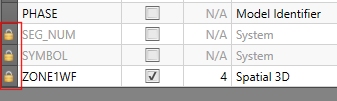
Otherwise, you can edit attribute details and Applythese changes and adjust all design data tables that currently use the attribute, and make corresponding changes throughout the file.
Depending on the complexity of your design data, this can take a while to complete. The status bar will show "Running script command" throughout the application process.
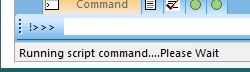
You will need to wait for the process to complete before applying other changes.
Applying Attributes Manually
This can be achieved by:
-
Creating New Attributes – Attributes can be added to the design by entering the desired attribute, and applying it using one of the available functions in your product.
-
Using Existing Attributes – Carries existing attributes from project design files to activities. Your application will add its own attributes to the design files as you progress through the advanced processes. For this reason, your application will prevent any unnecessary attributes from being carried across from the design files to the activities which are generated from the design files.
If any attributes are to be carried across from the design to their subsequent activities, they must be listed in the Attributes panel.
Manual attributes are applied using the Manual Attribute Assignment screen. Only attributes defined with an Application Method of Manual can be applied in this way.
Create Attributes from a File
You can generate attributes automatically from a file. This is done using the Generate button in the top left of the screen.
Use the File browser to select a file, then the Field Selector to choose which of the attributes in the file you want to use as design attributes.
Attributes Table Summary
Note: This screen includes table grids that support multiple row selection.
Attributes are presented in a single table. All attributes associated with the current project are listed. Some contents are editable whilst some fields, such as system fields, or cells that aren't relevant to a particular Application method (for example) are read-only.
The Attributes table contains the following information:
-
Name – The name of the attribute to be applied.
-
Alpha – The attribute type, either checked (alphanumeric) or unchecked (numeric). If this attribute already exists in a design file, this field must be specified exactly how it is in the design files.
-
Size – The number of characters an attribute can have if the attribute is of the alphanumeric type. This must be set exactly how the attribute is configured in the design file (if it already exists in a design file).
-
Application Method – How the attribute is to be applied to data. See Attribute Application Method, above, for information on each option.
-
Automatic Attribute Settings – Available for Solid, Grid and Filter attribute types (otherwise, "N/A" is displayed and the cell is locked), a summary of attribute settings is shown, for example, the number of rules representing a filter, or the attribute and value used to define a grid, for example.
Tip: Hover your mouse over an item in the Automatic Attribute Settings cell to see a more detailed view of the settings.
-
Export Type – If you export your attributes, the format in which they are stored is dependent on the selection made in this list.
-
Not Exported – Attributes are not exported.
-
Code Field – Export values relating to a range of integers.
-
Production field – Export the attribute to as a production field. Once an Attribute is defined like this, it cannot be defined as an alphanumeric attribute. If set, you can define a production unit, which must be unique to the table.
-
Text Field – Data is exported as a free-form field that can be of any format.
-
Related topics and activities