
CXS Design Type
Complex Solids are underground cavities which do not have uniform dimensions, such as a stope. This differs from a Fixed Cross-sectional (FXS) and outline (OUT) design types which have a uniform profile along the length of the target design string.
A complex solid is defined by two or more outlines. One of these outlines will define the lower area of the stope while the last of these outlines defines the upper area bounding the volume of the stope.
Complex solids, like other design types, are derived from design string data files (one or more) specified using the Project Settings task. This process involves defining a Group Identifier field; this is an important attribute that determines which data represents each distinct volume to be generated. This could be a stope number, for instance.
Once processed, complex solids will be generated as an in-memory wireframe object called "CXS Solids", which can be accessed using the Sheets control bar. This can be useful for visualizing/animating the resulting object to review the calculated segmentation and sequencing. A corresponding points file is also generated, which represents the location that will become the "activity" point for each segment. See Process Data Changes.
Note: Complex solids honour existing tag strings if any are found conjoining the perimeter design strings.
You can access generic data management functions throughout the design definition process.

Example of a two-string complex solid.
Design Definition Controls
You can add a new definition using the + icon at the top right of the panel. You can also copy an existing definition and edit it if you wish. The same button group also contains a delete definition button, but this is only possible if the definition is not locked (i.e. it hasn't already been subject to processing).

- Add a definition.
- Copy the selected activity definition to a new definition.
- Display the Bulk Field Change screen to make wholesale changes to all selected definitions (at least 2 definitions must be selected in the upper table.
- Delete the selected definitions.
Matching Attributes
In versions prior to version 2.1, Studio UG matched designs to definitions by the field DESIGNDF (the design definition Name). In these versions, you had to ensure you applied the design definition to your designs. Applying a design definition to a design would set the values of the DESIGNDF, COLOUR, LSTYLE, and SYMBOL columns. During processing, the design definition of a design was only matched by reading the values in the DESIGNDF column. This could lead to a mismatch between the value of DESIGNDF and the display Properties (COLOUR, LSTYLE, SYMBOL) if you modified the display properties of your designs without using the Apply Design Definitions feature. In effect, there was a risk of data duplication that could get out of sync.
In Studio UG version 2.1 and later designs are once again matched to design definitions by matching attribute values. This means that if the attribute values are on the design, you don't need to apply the design definition as it will automatically be matched during processing. The action of applying a design definition sets the matching attribute values on the designs so that the automatic matching will work. This provides more flexibility and can save significant amounts of time. If the designs already have the appropriate attribute values, you can jump straight to processing. To apply values to the matching attributes, you can use the Apply Design Definitions screen, standard Studio commands, or even use a script.
You can select one or more attribute definitions to use for matching. Each design definition must have a unique combination of values for the matching attributes. The matching attribute definitions are defined per design type. You can still match using the display properties (LSTYLE, COLOUR, SYMBOL), but you are no longer restricted to doing so. Matching on fields other than the display properties allows you to use the same design definition for designs that have different colours, for example. Activity Solids get their colour from their associated design, whether COLOUR is used in the attribute matching or not.
In a way this is how Studio 5D Planner worked: it was just hard-coded to match by the attributes COLOUR, LSTYLE, and SYMBOL. In Studio UG, this restriction is lifted.
Each design type must match on at least one attribute. You can choose to match on the system attributes COLOUR, LSTYLE, and SYMBOL or any of the user attributes. The design definition needs a unique name as well.
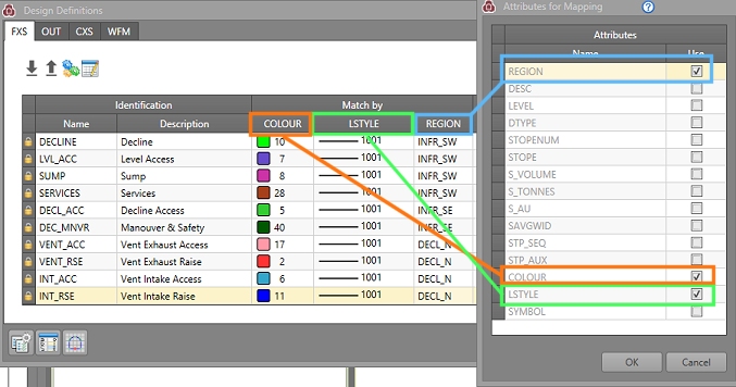
These "Match By" attributes are configured using the Attributes for Mapping panel, a simple field chooser that updates (and is synchronized with) the Edit Design Definitions table.
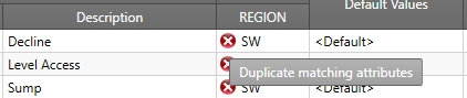
If it is not possible to create unique combinations of matching attributes for existing definitions, non-unique value combinations will be highlighted in the definitions table, for example:
The Solid colour will be taken from the design file, regardless of whether COLOUR is used in the attribute matching or not.
How Mapping Attributes are used in Generating Definitions
The Generate Design Definitions function is a useful tool that allows you to extract information from external files and use it to construct design definitions automatically.
This panel also honours the current mapping attributes to automatically extract definitions from the selected file. For example, if your mapping attributes are LSTYLE, COLOUR and SYMBOL, the Generate Design Definitions panel will automatically construct definitions based on all combinations of values found for these attributes in the file.
See Mapping Attributes.
See Generating Design Definitions.
Creating CXS Definitions
To configure a CXS design definition:
- Select Definitions from the Planning ribbon.
- In the Apply Design Definitions panel, click Edit Definitions.
- Select the Complex Solids tab.
- In the Design Definitions panel, select the Complex Solids tab.
-
Use the Design Definitions panel to edit or construct definitions manually, or Import them in from an external settings file (1), or Generate them from an existing Datamine table (3).
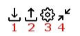
You can also Export your current settings for later use (2). To set up attribute matching, use Edit Matching Attributes (4)
- To create a new definition, you can either click the "+" in the top right of the panel, or extract a definition from an existing file using the Generate option. Whichever method is used, the Name field is editable up to 36 characters in length.
- Set a Name for the design definition - this must be unique amongst the table of definitions.
- Add a Description for the definition - this should describe the context in which the definition would be applied. This is the description that will appear in the Planning Report alongside the corresponding activities to which the definition has been used to create.
- Set the values for your previously-defined matching attributes. The combination of values for all columns under Match By must be unique for each definition.
- There are two segmenting methods available for
CXS design items;
- None will not segment the resulting solid - it will represent a single mining activity.
- Strings per Segment is used to specify how many strings make up the complex solid. If selected, you can access the Count field to determine the level of segmenting required. For example, by specifying [2], every 2 strings within the complex solid will be used to create an individual solid (activity). If a number less than or equal to [1] is specified, ALL strings within the complex solid will be utilized.
- Choose a preferred Mining Direction. Your product will reverse the calculated centreline if required to get closer to the preferred direction. Choose from:
- Not specified (default)
- North
- East
- South
- West
- Up
- Down
- Select your default value set from the Default Values column. This will contain, for example, the default DENSITY value for the selected design item.
- The Default Rate is the rate at which the complex solid will be mined. In the case of complex solids, you will need to specify a quantity, unit and time period in which the specified quantity is extracted.
- Under Default
Constraint you must also define whether a particular outline
design type is to be mined:
- As soon as possible
- As late as possible
-
Choose a Default Dependency Method. By default, activities will Start after latest predecessor, meaning they will continue from the most recently available (and appropriate) activity. You can choose Start after earliest predecessor instead, meaning the activity will start as soon as the first activity link reaches it.
Note: Default dependency method values can, depending on your transfer options, be exported to an schedule, and will be reflected in any dependency animations you run. See Transfer Data to DTS and Animate a DTS Schedule.
- The Exclude column is used to define sections of the design which will be excluded from the connection. This can be useful if there are construction lines within the design or when sections of the design have been mined.
-
Once all entities (that you wish to use in your project) have been fully defined, you can apply them to your project's design strings.
Click OK to dismiss the Design Definitions panel and return to the Apply Design Definitions panel.
- The list of all defined, imported and/or generated definitions will appear under the CXS tab (shown by default).
-
To apply your definition(s) to your design data, you first need to load the corresponding design type data into memory; click Load Designs. This will load all data that has been defined in Project Settings as CXS type.
If data is already loaded, this option will not be available and design strings will already be visible in the 3D window.
- Once you have applied all definitions to all required string entities, click Save Designs to update the Studio UG database.
-
Click Unload Designs to unload the current data set and move onto the next task.
Related topics and activities