
Design Files
Your underground planning projects are formed of a variety of data. Data that is ultimately destined for sequencing is categorized into 4 distinct data types.
Select a link below for more information on a particular type:
Fixed Cross Sectionals (FXS)

Solids processed from FXS string data
These design strings are used to produce solids by applying a fixed cross sectional area to a design string (survey line). See Fixed Cross Sectional Data.
Outlines (OUT)
Outlines are closed strings. Solids are processed by projecting the strings a set distance perpendicularly, or by projecting them to hanging-wall and foot-wall wireframes. See Outlines Data.
Complex Solids (CXS)
Solids are created by wireframing two closed strings which may be
irregular. See Complex Solids Data.
Imported Wireframes

Wireframes are volumes representing underground cavities, which typically do not
have uniform dimensions, such as stopes. Imported Wireframes are
wireframe files which have been imported from applications such
as Vulcan, or created in Studio 5D Planner/Studio UG using the
Mineable Shape Optimizer
(MSO) tool. See Imported Wireframes Data.
Configuring Design Files
Design files are the key input data around which a planning scenario
is defined.
You can define multiple files of the same design type. This greatly increases the options for collaboration
between different users and reduce the need for combination (merge)
of full projects. You will be able to process and sequence ore development
and stopes while the infrastructure and ventilation designs are still
work in progress, for example.
The geometry providing the basis for your underground design is contained
within one or more input Datamine binary files. Design files
are first specified, using the Project
Settings task, then design definitions are configured to indicate
what each element of your design data represents in the schedule (Edit
Design Definitions) and applied to the relevant data objects
(Apply
Definitions).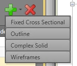
Design files are added using the green +
icon to select one of the project design types (Fixed Cross Sectional,
Outline, Complex Solid or Wireframe). This adds a new row to the Design
Files table below.
Once a design type is selected, select a file containing the design
data. You cannot select a file that already exists in the project.
Edit a design file source using the ellipsis button that will
appear if you click inside the File
Name field. This allows you to browse for an alternative file.
The Status of a design file
is either [Available] or [Not Found]. Any references to the latter
should be investigated as this indicates the specified file has either
been removed, relocated or renamed.
Complex Solids and Wireframe design types require a Group Identifier to be specified. This will be any attribute within the selected file (numeric or alphanumeric). Group Identifiers can be used for WFM or CXS objects to define which strings or triangles belong to the same solid.
Related topics and activities