
Open Pit Design
Designing an open pit is an iterative process involving consideration of many design criteria, constraints and objectives. There is no single way to design a pit - every engineer does it slightly differently. Our objective in this tutorial is to show in detail how to use the various design tools in Studio to create a detailed pit design using three different methods.
The design process starts from a geological resource or ore reserve which is defined by a block model.
The development of an ultimate pit design is often based on a series of interim pit phases that reflect successive cutbacks. This phased pit development allows the final pit wall design criteria to be based on the operational performance of each preceding phase. Lessons learned from any slope instability are applied to the design of subsequent mining phases. The understanding of geotechnical issues is progressively improved and the associated risk is reduced through the implementation of appropriate engineering designs and operating practices. To this end, observations and results from past and current experience should be applied to future mine planning.
Mine design is an interactive and continual process. In the early stages of development, mine design may change frequently due to exploration drilling of the ore body. In mature operations, mine designs change as the nature of the geotechnical limitations of pit wall segments and the influence of groundwater and storm water on the pit walls is better understood. Metal prices may change mine designs but they should not change slope angles, just the wall placements.
Key Open Pit Landmarks
Your application provides many tools for designing pits, dumps and other types of surface excavations. This introduction will identify some of these tools and suggest an approach to pit design.
Geometrical Components of a Slope
Drilling down a bit further (pun intended), the main geometrical components of a slope are referenced with respect to slope definition. Whilst determining the optimum/safest face slope angles that are appropriate for each region of the pit is outside the scope of Studio OP, implementing known regional slope constraints is very much part of the pit design workflow.
(Hustrulid et al., 2013a)
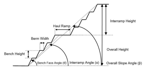
The main geometrical components of a slope are:
- Bench Face Angle – The angle between the horizontal plane and the bench wall. In most hard rock open pit mines, this parameter has values ranging between 55 and 80 degrees.
- Bench Height – The height, which typically has to adapt to the loading equipment operating the mine.
- Berm Width – The distance between the toe and crest of a bench.
- Inter-ramp Angle – The angle between the toe of a slope where a ramp segment passes and the toe of a bench located immediately upwards.
- Overall Slope Angle – The angle made with the horizontal of the line connecting the lowest toe to the uppermost crest.
- Global Slope Height – The height projected in the vertical axis between the lowest toe and the uppermost crest.
- Ramp – The road along which the trucks haul the material between a loading point and a destination.
Before considering the complex operations involved in open pit design it is useful to be familiar with some commonly-used string editing and wireframing utilities.
Manual Pit Design Methods
Before starting a detailed pit design, it is important to understand the existing surface topography, the extent and nature of the orebody, and the economic or ultimate pit limit of the mine. The method used will depend on the information available and the preferred design method.
The diagram below explains the meaning of many of the key terms
used in open pit mine design.
There are three key methods used to design open pits:
-
Toe + Ramp + Crest Design
-
Toe + Ramp Design
-
Contour Design
Toe + Ramp + Crest Design Method
The Toe + Ramp + Crest method is a bench by bench design method usually starting from the lowest bench and working upwards. Create the toe string, insert the ramp and finally add the crest strings. This method creates ramps that include access to the berms. It can be used either from the bottom up or from the top down.
The decision to start from the top or bottom of the deposit when designing the pit depends on the objective. Starting from the top is better for physical constraints to mining such as lease boundaries whereas starting from the bottom makes it easier to ensure that all the ore is extracted.
In this method the projection angles always relate to the face and batter angle.
Toe + Ramp Design Method
This method requires the creation of all the toe and ramp strings first and then the addition of the crest strings later. With this first step the projection angles used must be wall angles NOT FACE ANGLES. When all the ramp and toe strings have been positioned the projection angles should be changed to represent face and batter angles, and the crest strings for each bench should then be added to complete the design.
This method is quicker than the Toe + Ramp + Crest approach and it yields a continuous ramp with no offsets. However, it has the limitation that the pit design must be completed in the same session and the pit can only be designed from the bottom up.
Contour Design Method
The third technique involves inserting a ramp and crest strings into an existing set of toe strings. These toe strings are typically created by generating contours around an optimum pit shell block model.
Several of the Contour Design commands such as Road Between Contours (rbc) are also commonly used when modifying existing pit designs.
Manual Pit Design Commands
You application includes a series of interactive open pit design commands that can be used to fine-tune existing open pit data, although. Here are some examples of manual pit design commands. This is not an exhaustive list:
|
Menu Command |
Quick Key |
Description |
|
rseg |
Create a road (ramp) segment between two RLs. |
|
|
rcon |
Build a contour string by projecting a toe string a set distance. |
|
|
rbe |
Create a berm string offset a fixed distance from a crest contour. |
|
|
fng |
Set a fixed face angle that is used by the Road Segment, Road Contour and Project String commands. |
|
|
sbw |
Set a fixed berm width which is used by the Road Berm command. |
|
|
nr |
Create a new rosette. |
|
|
dro |
Delete a rosette. |
|
|
tur |
Use rosettes to define projection angles instead of the hard coded values. |
|
|
stro |
Build a road outline string from a single road design string. |
|
|
rbc |
Build a single road design string between two contour strings. |
|
|
crs |
Create a single ramp string based on user defined azimuth, gradient and distance criteria. |
Automated Pit Design
Your application provides a wide range of options for pit design, and a combination of automatic and interactive commands. The purpose of Studio OP's interactive pit modelling functions is to enable engineers to rapidly produce and evaluate alternative open pit mine designs based on strategic plans and to refine the designs as mining progresses.
A workflow enables even a relatively inexperienced engineer to design a set of pits based on the pushbacks that define a strategic plan. Using an appropriate starting point (planning model, ultimate pit shell, pit design strings and so on), you choose what happens next.
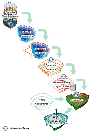
Automated pit design is completed in stages, roughly in the order shown here:
- Regional slope control is configured through the definition of pit regions, and optionally even more detailed control using rosettes. See Geotechnical Control in Automated Pit Design.
- Pit constraint perimeters (phase shell contours) are generated based on the contents of a block model, contour strings or other imported data. See Generate Pit Contours.
-
An unconstrained pit is projected automatically using a top-down or bottom-up approach, using a pit rim or base string as a starting point. See Auto Pit Design.
Note: tools also exist for automating the design of dumps and stockpiles. See Dynamic Dump Design.
- Automatic generation of in-pit roads, including surface roads.
Automated pit design functionality is linked tightly with the Reserves Workflow.
Define your pit, model and bench parameters once and these project elements are automatically made available to the interactive design facilities available on the Design ribbon. Working from a single database ensures there is only ever one version of the truth. There are stacks of options available to test different design paradigms and react quickly to newly-discovered mining requirements or constraints.
How you progress your pit design is up to you. The diagram below summarizes the possible steps of the Reserves Workflow:
Viewing Managed Data
The various tasks of automated pit design both consume and produce data. Much of this data is geometrical and can be displayed using the Task window (not the typical 3D data viewing windows).
The data each task create are deliberately segregated from the usual 3D window data in order to reduce lengthy lists of objects and to ensure that only data relevant to the task being performed is displayed.
Related topics and activities