|
|
Designing a Switchback Quickpit: creating a switchback ramp |

Overview
In this part of the tutorial you are going to use the Quickpit utility to create switchback, consisting of ramp, crest and toe strings.
|
Quickpit enables an iterative design process whereby the design of a pit can be altered (ramp positions, gradients, berms etc.) to find the best results. Additional optional functionality, over and above the manual toe-ramp-crest method covered in the Toe-Ramp-Crest Method section, includes:
These features improve the generated pit designs and minimizes the need for manual adjustments while designing. Other improvements to the process ensure that there are few overlaps where road segments start and end. This means the generation of a DTM of the pit is quicker. |
Prerequisites
Required:
-
Created a new project and added all the required tutorial files i.e. the exercises on the Creating a New Project page.
-
Loaded and viewed the ultimate pit shell model data i.e. the exercises on the Viewing Ultimate Pit Shell Models page.
-
Created and applied a custom legend, filtered cells, for the NPVS block model i.e. the exercises on the Creating a Custom Display Legend page.
Recommended:
-
Specified project and mine design settings i.e. the exercises on the Specifying Design Settings page.
-
Created a pit base string i.e. the exercises on the Creating a Pit Base String page.
Files required for the exercises on this page:
-
_vb_npvmod1
-
_vb_q_pit80adj
Link to Exercises
The following exercises are available on this page:
Exercise: Designing a Switchback
In this exercise you are going to use the pit design strings object _vb_q_pit80adj as a starting point for creating a switchback which exits towards the south, consisting of a set of ramp, crest and toe strings, in a single run of Quick Pit. This includes the following tasks:
-
Defining data and design plane settings
-
Using Quick Pit to generate a switchback
-
Saving the design strings to a Datamine file.
|
|
When using QUICKPIT you must always start with a closed string that represents a toe, pit base or pit top. |
Defining Data and Design Plane Settings
-
Select the Design window.
-
In the Project Files control bar, Strings folder, drag-and-drop the following file into the 3D window:
-
_vb_q_pit80adj
-
-
In the Sheets control bar, Design Overlays folder, select only the following overlays (i.e. display these overlays):
-
Default Grid
-
_vb_q_pit80adj
-
_vb_npvmod1 (block model)
-
-
In the Loaded Data control bar, unload all other strings objects.
-
In the View Control toolbar, click Zoom All Data.
-
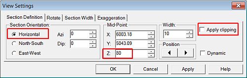
In the View Control toolbar, click View Settings.
-
In the View Settings dialog, define the Section Orientation and Mid-Point XYZ coordinate ( elevation 80) parameters shown below, click OK:
-
In the View Control toolbar, click Zoom In.
-
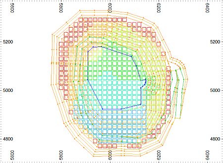
In the Design window, drag a zoom rectangle to display the view extents shown below:
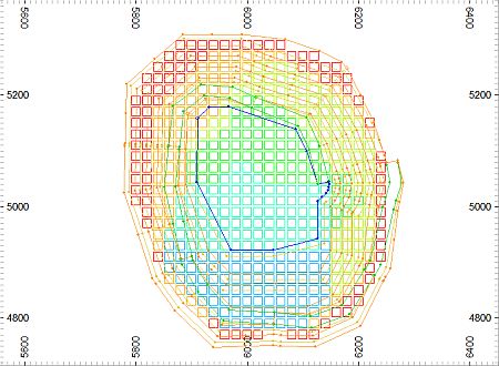
")
In the above image, the 80m elevation toe string has already been adjusted outwards to include the displayed ore cells on the north-eastern side of the pit.
Using Quick Pit to Generate A Switchback
-
In the Design window, right-click and select Deselect All Strings (das).
-
Select Applications | Open Pit | Open Pit Design Utility.
You could also type 'QUICKPIT' at the command line in the Command toolbar.
-
In the Customization control bar, the Quick Pit Design dialog, define the settings listed below:
-
Project: Up
-
Expand: Out
-
Project: 1 : Times
-
Bench\Flitch Height: 20
-
Berm Interval: 1
-
Ref Elevation: leave blank
-
Face Angle: 60
-
Interramp Angle: 45.6562
-
Berm Width: 8
-
Include Road: Select
-
Road Width: 20
-
Road Gradient: 10
-
Direction: Clockw(ise)
-
Settings:
-
-
Adjust Road Entrance: Select
-
Auto Fillet: Clear
-
Automatic Crossover Checking: Select
-
Automatic Conditioning: Select
-
Taper Berms: Select
-
Move Plane after projection: Select
-
-
-
Check that your settings are as shown below , click OK:
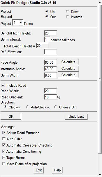
As an alternative to changing the Direction from anticlockwise to clockwise, the Choose Dir(ection) option could also be used.
For the settings Face Angle, Berm Width and Interramp Angle you can enter values for two of these parameters and select the associated Calculate button to calculate the third value.
-
For the next steps, follow the prompt dialogs and corresponding messages in the Status Bar.
-
When prompted, click OK, select (left-click) the orange 80m elevation toe string in the Design window.
-
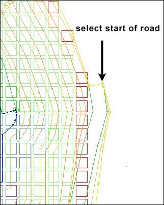
When prompted, click OK, select (left-click) the start point for the road as shown below:
-
Wait for the design strings to be generated, then in the Design window, right-click and select Deselect All Strings (das).
-
Check that the switchback bench (i.e. with the ramp now heading south), consisting of a ramp, crest and toe string, has been created:
-
In the Loaded Data control bar, check that a new Design Strings object is listed.
This object contains the pit design strings i.e. the selected pit base string and the newly generated ramp, crest and toe strings that have been generated by the Quick Pit Design utility.
-
In the 3D window, pan, rotate and zoom the view and check that the switchback and adjusted toe access area has been created as shown below:
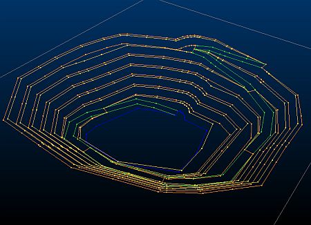
In the above image, the block model has been hidden in order to show the design strings more clearly.
Saving the Design Strings to a Datamine File
-
In the Loaded Data control bar, right-click on the Design Strings object, select Data | Save As.
-
In the Save New 3D Object dialog, click OK.
-
In the Save New Strings dialog, select the path to you tutorial folder, define the File name: as 'q_pit100', click Save.
-
In the Loaded Data control bar, check that the Design Strings object has been replaced by the object q_pit100 (strings).
-
Select File | Save.
|
You can check your design strings against the example file _vb_q_pit100 (strings).dm. |
Copyright © CAE Inc.
MIN 20048_00_EN