|
|
Generating Toe-Ramp Benches Toe-ramp method: generating the ramp and toe strings |

Overview
In this part of the tutorial you are going to use a pit base string (toe string) as a starting point for creating a few sets of toe-ramp strings.
|
The Toe-Ramp design method involves first creating all the toe and ramp strings and then adding the crest strings. This method is quicker than the Toe-Ramp-Crest approach and yields a continuous ramp with no offsets on the berms. A toe-ramp design sequence starts and ends with a toe string. If you are not happy with the design at any stage, you can erase the incorrect strings and recreate them using the open pit design commands. The design MUST be restarted from toe string, NOT from a road segment. |
Prerequisites
Required:
-
Created a new project and added all the required tutorial files i.e. the exercises on the Creating a New Project page.
-
Loaded and viewed the ultimate pit shell model data i.e. the exercises on the Viewing Ultimate Pit Shell Models page.
-
Created and applied a custom legend, filtered cells, for the NPVS block model i.e. the exercises on the Creating a Custom Display Legend page.
Recommended:
-
Specified project and mine design settings i.e. the exercises on the Specifying Design Settings page.
-
Created a pit base string i.e. the exercises on the Creating a Pit Base String page.
-
The Toe-Ramp-Crest method exercises.
Files required for the exercises on this page:
-
_vb_npvmod1
-
_vb_pitbase-40
Exercise: Creating the First Bench
In this exercise you are going to use the pit base string _vb_pitbase-40 as a starting point for creating the ramp string for the first (lowest) bench i.e. the -20m bench, which will be 20m high. This includes the following tasks:
-
Defining data and design plane settings
-
Saving to a new strings file
-
Setting the projection angle
-
Creating the ramp
-
Editing the toe
-
Moving up a bench
-
Creating the next toe
-
Moving the toe out
-
Adjusting and conditioning the toe string
-
Saving the data.
|
The face angle and berm width can be changed at any time during the design process. |
Defining Data and Design Plane Settings
-
If you have any data loaded, unload it with the quick key 'ua'.
-
In the Project Files control bar, All Tables folder, drag-and-drop the following file into the 3D window:
-
_vb_pitbase-40
-
_vb_npvmod1
-
-
Double-click the 3D window background (any empty space) and set the background to a fixed white colour.
-
In the Sheets control bar, select only the following 3D overlays:
-
Default Grid
-
_vb_pitbase-40 (strings)
-
_vb_npvmod1 (block model)
-
-
Use the quick key 'za' to zoom all data.
-
Expand the Sections folder and double click the [Default Section] item to display the Default Section Properties dialog.
-
If they aren't set up already, define the Section Orientation as [Horizontal] and Mid-Point XYZ coordinate (6110, 5100, -40) parameters.
-
Use the View ribbon and click Align.
-
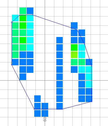
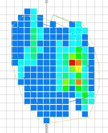
In the 3D window, drag a zoom rectangle to display the view extents shown below:
Saving To a New Strings File
-
In the Loaded Data control bar, right-click on the _vb_pitbase-40 (strings) object, select Data | Save As.
- In the Save New 3D Object dialog, click Extended Precision Datamine (.dm) File.
- In the Save New Strings dialog, select the path to your tutorial folder 'C:/Database/MyTutorials/OPDesign', define the File name: as 'tr_pit0.dm', click Save.
- In the Loaded Data control bar, check that _vb_pitbase-40 (strings) has been replaced by tr_pit0 (strings).
- Check that tr_pit0 (strings)
is the current strings object i.e. highlighted bold.
")
Here, using the toe-ramp method, we are designing from one crest to another and so the output file name reflects the ramp and toe strings up to and including the -20m elevation.
Setting the Projection Angle
|
When using the Toe-Ramp method, the default face angle setting needs to be set to the overall pit wall slope and not the slope of a bench face, when creating the ramp and toe strings; here the overall slope angle is 50 degrees. This angle needs to be set back to the bench face angle (in this tutorial, 60 degrees) when adding the crest strings. |
-
Activate the Design ribbon and select Design | Face Angle.
-
In the Studio OP dialog, check that the default face angle is '50' degrees, click OK.
Creating a Ramp
-
In the 3D window, right-click and select Deselect All Strings (das).
-
Using the Design ribbon select Design | Road Segment.
-
Follow the messages displayed on the left side of the Status Bar for the steps below.
-
In the 3D window, select (left-click) the blue pit base perimeter string (this step selects the toe string).
-
Click at a location outside of the base perimeter (this step defines the high side i.e. crest side, of the toe string).
-
In the Studio OP (Road Segment) dialog, define the settings as follows, click OK:
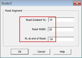
RL at end of road is the elevation at the top of the ramp.
-
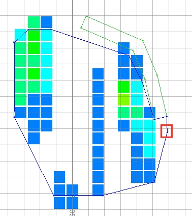
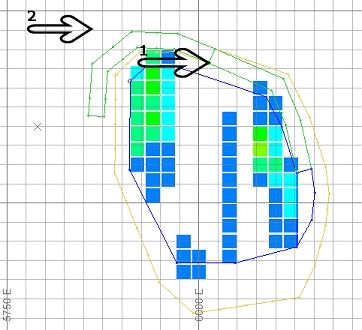
As shown below, left-click close to the toe string point and then left-click at a location approximately 20m to the north:
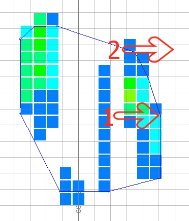
The first point defines the inside corner of the ramp and must be snapped to the toe string; the second point indicates the upwards direction of the ramp i.e. north.
-
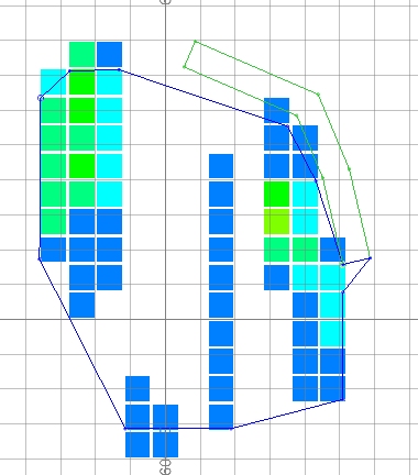
In the 3D window, right-click and Deselect all strings, then check that a green ramp string has been created as shown below:
Editing the Toe String at the Ramp
-
Activate the Edit ribbon.
-
Select Attributes | Edit Coordinate and left-click the first string point south of the ramp (the one directly below position 1 in the image shown in step 7).
-
Increase the X coordinate by 20m, making it "6147.342" and click OK:
-
Use the quick key 'ipo' (insert points)
-
Place a new point roughly 30m south of the point that has just been moved, click Done.
-
In the 3D window, check that your two toe string points south of the ramp are similar to what is shown below:
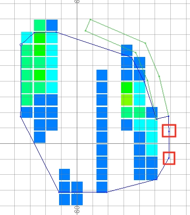
Do not edit the green road string, as the points on this string contain special control information required for the next stage in the design. If you are unhappy about the shape of the road string, the entire road string should be erased (ers) and the shape of the toe string it is projected from should be modified.
Moving Up A Bench
-
Activate the View ribbon and click Sections | Forward twice to move the section 20m upwards from its -40 setting to become -20.
-
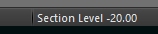
You can see the section level at the bottom of the Studio OP interface, in the Status bar:
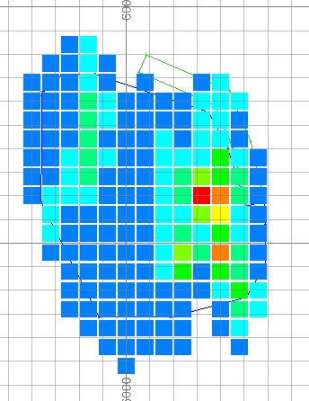
-
You can now see the model cells of the -20 elevation, plus the previous string data:
Creating the Next Toe
|
In the Toe-Ramp method, the Create Road Contour command is used to generate toe strings without a berm offset at the top of the ramp; in the Toe-Ramp-Crest method, the Create Road Berm command is used to create the offset toe strings. |
-
Activate the Design ribbon and click Design | Contour.
-
Select the blue, closed toe string using the left mouse button.
-
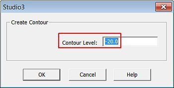
In the Studio OP (Create Contour) dialog, make sure the contour elevation is '-20', click OK:
-
In the 3D window, right-click and select Deselect All Strings (das).
-
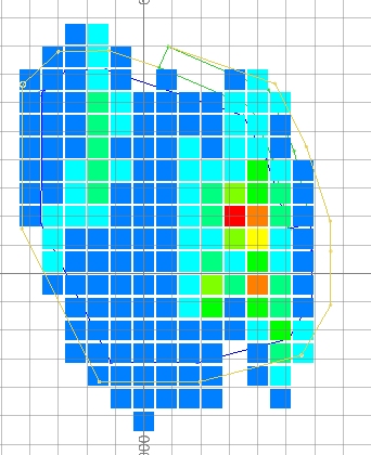
Check that the yellow toe string (perimeter) has been created as shown below, noting the position of the string at the top of the ramp:
Adjusting and Conditioning the Toe String
-
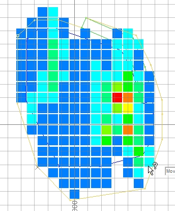
In the 3D window, using Move Points, adjust the yellow toe string in the southern portion of the pit, outwards to include the ore cells, as indicated below:
Don't forget to click Done to complete the point moving command. -
Select the adjusted orange toe string then select the Edit ribbon's Condition command.
-
In the Studio OP (Condition String) dialog, define the settings shown below, click OK:
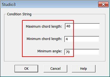
The string will be conditioned so that all chords (segments) are between 4 and 40 metres in length and no internal string angle will be less than 70 degrees.
-
In the 3D window, left-click away from the string data to deselect the conditioned toe string. You will see that it now includes additional vertices.
-
Check that the conditioned toe string is as shown below:
-
Save your project and click OK.
|
You can check your design strings against the example file _vb_tr_pit-20.dm. |
Creating the Next Ramp and Toe
-
Using the techniques covered in the above sections, generate the next set of ramp and toe strings to end at 0m elevation. Using the same projection angle, you need to:
-
Select the outermost design string and Design | Road Segment. Gradient = 10, Road Width = 20, RL at end of Road = 0.
-
When asked to point to the start of the road, left click the inside edge of the end of the new green road.
-
Select another point outside the pit in an anticlockwise direction to create the new road i.e.:
-
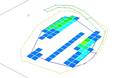
Zoom and rotate the view to see the new road extension:
-
Save your project and data.
|
You can check your design strings against the example file _vb_tr_pit0.dm. |
Copyright © Datamine Corporate Limited
JMN 20048_00_EN